Virtual Tenant Network (VTN)

VTN Overview

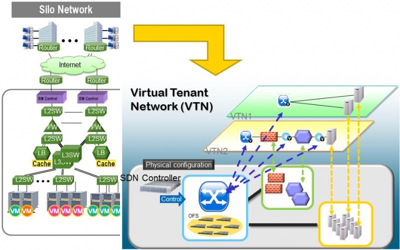
OpenDaylight Virtual Tenant Network (VTN) is an application that provides multi-tenant virtual network on an SDN controller.

Conventionally, huge investment in the network systems and operating expenses are needed because the network is configured as a silo for each department and system. So, various network appliances must be installed for each tenant and those boxes cannot be shared with others. It is a heavy work to design, implement and operate the entire complex network.

The uniqueness of VTN is a logical abstraction plane. This enables the complete separation of logical plane from physical plane. Users can design and deploy any desired network without knowing the physical network topology or bandwidth restrictions.

VTN allows the users to define the network with a look and feel of conventional L2/L3 network. Once the network is designed on VTN, it will automatically be mapped into underlying physical network, and then configured on the individual switch leveraging SDN control protocol. The definition of logical plane makes it possible not only to hide the complexity of the underlying network but also to better manage network resources. It achieves reducing reconfiguration time of network services and minimizing network configuration errors.

VTN Overview

VTN Overview

It is implemented as two major components

  • VTN Manager
  • VTN Coordinator

VTN Manager

An OpenDaylight Plugin that interacts with other modules to implement the components of the VTN model. It also provides a REST interface to configure VTN components in OpenDaylight. VTN Manager is implemented as one plugin to the OpenDaylight. This provides a REST interface to create/update/delete VTN components. The user command in VTN Coordinator is translated as REST API to VTN Manager by the OpenDaylight Driver component. In addition to the above mentioned role, it also provides an implementation to the OpenStack L2 Network Functions API.

Features Overview

  • odl-vtn-manager provides VTN Manager’s JAVA API.
  • odl-vtn-manager-rest provides VTN Manager’s REST API.
  • odl-vtn-manager-neutron provides the integration with Neutron interface.

REST API

VTN Manager provides REST API for virtual network functions.

Here is an example of how to create a virtual tenant network.

curl --user "admin":"admin" -H "Accept: application/json" -H \
"Content-type: application/json" -X POST \
http://localhost:8181/restconf/operations/vtn:update-vtn \
-d '{"input":{"tenant-name":"vtn1"}}'

You can check the list of all tenants by executing the following command.

curl --user "admin":"admin" -H "Accept: application/json" -H \
"Content-type: application/json" -X GET \
http://localhost:8181/restconf/operational/vtn:vtns

REST Conf documentation for VTN Manager, please refer to: https://nexus.opendaylight.org/content/sites/site/org.opendaylight.vtn/boron/manager.model/apidocs/index.html

VTN Coordinator

The VTN Coordinator is an external application that provides a REST interface for an user to use OpenDaylight VTN Virtualization. It interacts with VTN Manager plugin to implement the user configuration. It is also capable of multiple OpenDaylight orchestration. It realizes Virtual Tenant Network (VTN) provisioning in OpenDaylight instances. In the OpenDaylight architecture VTN Coordinator is part of the network application, orchestration and services layer. VTN Coordinator will use the REST interface exposed by the VTN Manger to realize the virtual network using OpenDaylight. It uses OpenDaylight APIs (REST) to construct the virtual network in OpenDaylight instances. It provides REST APIs for northbound VTN applications and supports virtual networks spanning across multiple OpenDaylight by coordinating across OpenDaylight.

For VTN Coordinator REST API, please refer to: https://wiki.opendaylight.org/view/OpenDaylight_Virtual_Tenant_Network_%28VTN%29:VTN_Coordinator:RestApi

Network Virtualization Function

The user first defines a VTN. Then, the user maps the VTN to a physical network, which enables communication to take place according to the VTN definition. With the VTN definition, L2 and L3 transfer functions and flow-based traffic control functions (filtering and redirect) are possible.

Virtual Network Construction

The following table shows the elements which make up the VTN. In the VTN, a virtual network is constructed using virtual nodes (vBridge, vRouter) and virtual interfaces and links. It is possible to configure a network which has L2 and L3 transfer function, by connecting the virtual intrefaces made on virtual nodes via virtual links.

vBridge The logical representation of L2 switch function.
vRouter The logical representation of router function.
vTep The logical representation of Tunnel End Point - TEP.
vTunnel The logical representation of Tunnel.
vBypass The logical representation of connectivity between controlled networks.
Virtual interface The representation of end point on the virtual node.
Virtual Linkv(vLink) The logical representation of L1 connectivity between virtual interfaces.

The following figure shows an example of a constructed virtual network. VRT is defined as the vRouter, BR1 and BR2 are defined as vBridges. interfaces of the vRouter and vBridges are connected using vLinks.

VTN Construction

VTN Construction

Mapping of Physical Network Resources

Map physical network resources to the constructed virtual network. Mapping identifies which virtual network each packet transmitted or received by an OpenFlow switch belongs to, as well as which interface in the OpenFlow switch transmits or receives that packet. There are two mapping methods. When a packet is received from the OFS, port mapping is first searched for the corresponding mapping definition, then VLAN mapping is searched, and the packet is mapped to the relevant vBridge according to the first matching mapping.

Port mapping Maps physical network resources to an interface of vBridge using Switch ID, Port ID and VLAN ID of the incoming L2 frame. Untagged frame mapping is also supported.
VLAN mapping Maps physical network resources to a vBridge using VLAN ID of the incoming L2 frame.Maps physical resources of a particular switch to a vBridge using switch ID and VLAN ID of the incoming L2 frame.
MAC mapping Maps physical resources to an interface of vBridge using MAC address of the incoming L2 frame(The initial contribution does not include this method).

VTN can learn the terminal information from a terminal that is connected to a switch which is mapped to VTN. Further, it is possible to refer that terminal information on the VTN.

  • Learning terminal information VTN learns the information of a terminal that belongs to VTN. It will store the MAC address and VLAN ID of the terminal in relation to the port of the switch.
  • Aging of terminal information Terminal information, learned by the VTN, will be maintained until the packets from terminal keep flowing in VTN. If the terminal gets disconnected from the VTN, then the aging timer will start clicking and the terminal information will be maintained till timeout.

The following figure shows an example of mapping. An interface of BR1 is mapped to port GBE0/1 of OFS1 using port mapping. Packets received from GBE0/1 of OFS1 are regarded as those from the corresponding interface of BR1. BR2 is mapped to VLAN 200 using VLAN mapping. Packets with VLAN tag 200 received from any ports of any OFSs are regarded as those from an interface of BR2.

VTN Mapping

VTN Mapping

vBridge Functions

The vBridge provides the bridge function that transfers a packet to the intended virtual port according to the destination MAC address. The vBridge looks up the MAC address table and transmits the packet to the corresponding virtual interface when the destination MAC address has been learned. When the destination MAC address has not been learned, it transmits the packet to all virtual interfaces other than the receiving port (flooding). MAC addresses are learned as follows.

  • MAC address learning The vBridge learns the MAC address of the connected host. The source MAC address of each received frame is mapped to the receiving virtual interface, and this MAC address is stored in the MAC address table created on a per-vBridge basis.
  • MAC address aging The MAC address stored in the MAC address table is retained as long as the host returns the ARP reply. After the host is disconnected, the address is retained until the aging timer times out. To have the vBridge learn MAC addresses statically, you can register MAC addresses manually.

vRouter Functions

The vRouter transfers IPv4 packets between vBridges. The vRouter supports routing, ARP learning, and ARP aging functions. The following outlines the functions.

  • Routing function When an IP address is registered with a virtual interface of the vRouter, the default routing information for that interface is registered. It is also possible to statically register routing information for a virtual interface.
  • ARP learning function The vRouter associates a destination IP address, MAC address and a virtual interface, based on an ARP request to its host or a reply packet for an ARP request, and maintains this information in an ARP table prepared for each routing domain. The registered ARP entry is retained until the aging timer, described later, times out. The vRouter transmits an ARP request on an individual aging timer basis and deletes the associated entry from the ARP table if no reply is returned. For static ARP learning, you can register ARP entry information manually.
  • DHCP relay agent function The vRouter also provides the DHCP relay agent function.

Flow Filter Functions

Flow Filter function is similar to ACL. It is possible to allow or prohibit communication with only certain kind of packets that meet a particular condition. Also, it can perform a processing called Redirection - WayPoint routing, which is different from the existing ACL. Flow Filter can be applied to any interface of a vNode within VTN, and it is possible to the control the packets that pass interface. The match conditions that could be specified in Flow Filter are as follows. It is also possible to specify a combination of multiple conditions.

  • Source MAC address
  • Destination MAC address
  • MAC ether type
  • VLAN Priority
  • Source IP address
  • Destination IP address
  • DSCP
  • IP Protocol
  • TCP/UDP source port
  • TCP/UDP destination port
  • ICMP type
  • ICMP code

The types of Action that can be applied on packets that match the Flow Filter conditions are given in the following table. It is possible to make only those packets, which match a particular condition, to pass through a particular server by specifying Redirection in Action. E.g., path of flow can be changed for each packet sent from a particular terminal, depending upon the destination IP address. VLAN priority control and DSCP marking are also supported.

Action Function
Pass Pass particular packets matching the specified conditions.
Drop Discards particular packets matching the specified conditions.
Redirection Redirects the packet to a desired virtual interface. Both Transparent Redirection (not changing MAC address) and Router Redirection (changing MAC address) are supported.

The following figure shows an example of how the flow filter function works.

If there is any matching condition specified by flow filter when a packet being transferred within a virtual network goes through a virtual interface, the function evaluates the matching condition to see whether the packet matches it. If the packet matches the condition, the function applies the matching action specified by flow filter. In the example shown in the figure, the function evaluates the matching condition at BR1 and discards the packet if it matches the condition.

VTN FlowFilter

VTN FlowFilter

Multiple SDN Controller Coordination

With the network abstractions, VTN enables to configure virtual network across multiple SDN controllers. This provides highly scalable network system.

VTN can be created on each SDN controller. If users would like to manage those multiple VTNs with one policy, those VTNs can be integrated to a single VTN.

As a use case, this feature is deployed to multi data center environment. Even if those data centers are geographically separated and controlled with different controllers, a single policy virtual network can be realized with VTN.

Also, one can easily add a new SDN Controller to an existing VTN or delete a particular SDN Controller from VTN.

In addition to this, one can define a VTN which covers both OpenFlow network and Overlay network at the same time.

Flow Filter, which is set on the VTN, will be automatically applied on the newly added SDN Controller.

Coordination between OpenFlow Network and L2/L3 Network

It is possible to configure VTN on an environment where there is mix of L2/L3 switches as well. L2/L3 switch will be shown on VTN as vBypass. Flow Filter or policing cannot be configured for a vBypass. However, it is possible to treat it as a virtual node inside VTN.

Virtual Tenant Network (VTN) API

VTN provides Web APIs. They are implemented by REST architecture and provide the access to resources within VTN that are identified by URI. User can perform the operations like GET/PUT/POST/DELETE against the virtual network resources (e.g. vBridge or vRouter) by sending a message to VTN through HTTPS communication in XML or JSON format.

VTN API

VTN API

Function Outline

VTN provides following operations for various network resources.

Resources GET POST PUT DELETE
VTN Yes Yes Yes Yes
vBridge Yes Yes Yes Yes
vRouter Yes Yes Yes Yes
vTep Yes Yes Yes Yes
vTunnel Yes Yes Yes Yes
vBypass Yes Yes Yes Yes
vLink Yes Yes Yes Yes
Interface Yes Yes Yes Yes
Port map Yes No Yes Yes
Vlan map Yes Yes Yes Yes
Flowfilter (ACL/redirect) Yes Yes Yes Yes
Controller information Yes Yes Yes Yes
Physical topology information Yes No No No
Alarm information Yes No No No

Example usage

The following is an example of the usage to construct a virtual network.

  • Create VTN
 curl --user admin:adminpass -X POST -H 'content-type: application/json'  \
-d '{"vtn":{"vtn_name":"VTN1"}}' http://172.1.0.1:8083/vtn-webapi/vtns.json
  • Create Controller Information
 curl --user admin:adminpass -X POST -H 'content-type: application/json'  \
-d '{"controller": {"controller_id":"CONTROLLER1","ipaddr":"172.1.0.1","type":"odc","username":"admin", \
"password":"admin","version":"1.0"}}' http://172.1.0.1:8083/vtn-webapi/controllers.json
  • Create vBridge under VTN
curl --user admin:adminpass -X POST -H 'content-type: application/json' \
-d '{"vbridge":{"vbr_name":"VBR1","controller_id": "CONTROLLER1","domain_id": "(DEFAULT)"}}' \
http://172.1.0.1:8083/vtn-webapi/vtns/VTN1/vbridges.json
  • Create the interface under vBridge
curl --user admin:adminpass -X POST -H 'content-type: application/json' \
-d '{"interface":{"if_name":"IF1"}}' http://172.1.0.1:8083/vtn-webapi/vtns/VTN1/vbridges/VBR1/interfaces.json

VTN OpenStack Configuration

This guide describes how to set up OpenStack for integration with OpenDaylight Controller.

While OpenDaylight Controller provides several ways to integrate with OpenStack, this guide focus on the way which uses VTN features available on OpenDaylight. In the integration, VTN Manager work as network service provider for OpenStack.

VTN Manager features, enable OpenStack to work in pure OpenFlow environment in which all switches in data plane are OpenFlow switch.

Requirements

  • OpenDaylight Controller. (VTN features must be installed)
  • OpenStack Control Node.
  • OpenStack Compute Node.
  • OpenFlow Switch like mininet(Not Mandatory).

The VTN features support multiple OpenStack nodes. You can deploy multiple OpenStack Compute Nodes. In management plane, OpenDaylight Controller, OpenStack nodes and OpenFlow switches should communicate with each other. In data plane, Open vSwitches running in OpenStack nodes should communicate with each other through a physical or logical OpenFlow switches. The core OpenFlow switches are not mandatory. Therefore, you can directly connect to the Open vSwitch’s.

Openstack Overview

Openstack Overview

Sample Configuration

Below steps depicts the configuration of single OpenStack Control node and OpenStack Compute node setup. Our test setup is as follows

LAB Setup

LAB Setup

Server Preparation

  • Install Ubuntu 14.04 LTS in two servers (OpenStack Control node and Compute node respectively)
  • While installing, Ubuntu mandates creation of a User, we created the user “stack”(We will use the same user for running devstack)
  • Proceed with the below mentioned User Settings and Network Settings in both the Control and Compute nodes.

User Settings for devstack - Login to both servers - Disable Ubuntu Firewall

sudo ufw disable
  • Install the below packages (optional, provides ifconfig and route coammnds, handy for debugging!!)

    sudo apt-get install net-tools
    
  • Edit sudo vim /etc/sudoers and add an entry as follows

    stack ALL=(ALL) NOPASSWD: ALL
    

Network Settings - Checked the output of ifconfig -a, two interfaces were listed eth0 and eth1 as indicated in the image above. - We had connected eth0 interface to the Network where OpenDaylight is reachable. - eth1 interface in both servers were connected to a different network to act as data plane for the VM’s created using the OpenStack. - Manually edited the file : sudo vim /etc/network/interfaces and made entries as follows

 stack@ubuntu-devstack:~/devstack$ cat /etc/network/interfaces
 # This file describes the network interfaces available on your system
 # and how to activate them. For more information, see interfaces(5).
 # The loop-back network interface
 auto lo
 iface lo inet loopback
 # The primary network interface
 auto eth0
 iface eth0 inet static
      address <IP_ADDRESS_TO_REACH_ODL>
      netmask <NET_MASK>
      broadcast <BROADCAST_IP_ADDRESS>
      gateway <GATEWAY_IP_ADDRESS>
auto eth1
iface eth1 inet static
     address <IP_ADDRESS_UNIQ>
     netmask <NETMASK>

Note

Please ensure that the eth0 interface is the default route and it is able to reach the ODL_IP_ADDRESS NOTE: The entries for eth1 are not mandatory, If not set, we may have to manually do “ifup eth1” after the stacking is complete to activate the interface

Finalize the user and network settings - Please reboot both nodes after the user and network settings to have the network settings applied to the network - Login again and check the output of ifconfig to ensure that both interfaces are listed

OpenDaylight Settings and Execution

VTN Configuration for OpenStack Integration:

  • VTN uses the configuration parameters from “90-vtn-neutron.xml” file for the OpenStack integration.

  • These values will be set for the OpenvSwitch, in all the participating OpenStack nodes.

  • A configuration file “90-vtn-neutron.xml” will be generated automatically by following the below steps,

  • Download the latest Boron karaf distribution from the below link,

    http://www.opendaylight.org/software/downloads
    
  • cd “distribution-karaf-0.5.0-Boron” and run karaf by using the following command ”./bin/karaf”.

  • Install the below feature to generate “90-vtn-neutron.xml”

feature:install odl-vtn-manager-neutron
  • Logout from the karaf console and Check “90-vtn-neutron.xml” file from the following path “distribution-karaf-0.5.0-Boron/etc/opendaylight/karaf/”.
  • The contents of “90-vtn-neutron.xml” should be as follows:

bridgename=br-int portname=eth1 protocols=OpenFlow13 failmode=secure

  • The values of the configuration parameters must be changed based on the user environment.
  • Especially, “portname” should be carefully configured, because if the value is wrong, OpenDaylight fails to forward packets.
  • Other parameters works fine as is for general use cases.
    • bridgename
      • The name of the bridge in Open vSwitch, that will be created by OpenDaylight Controller.
      • It must be “br-int”.
    • portname
      • The name of the port that will be created in the vbridge in Open vSwitch.
      • This must be the same name of the interface of OpenStack Nodes which is used for interconnecting OpenStack Nodes in data plane.(in our case:eth1)
      • By default, if 90-vtn-neutron.xml is not created, VTN uses ens33 as portname.
    • protocols
      • OpenFlow protocol through which OpenFlow Switch and Controller communicate.
      • The values can be OpenFlow13 or OpenFlow10.
    • failmode
      • The value can be “standalone” or “secure”.
      • Please use “secure” for general use cases.

Start ODL Controller

  • Please refer to the Installation Pages to run ODL with VTN Feature enabled.
  • After running ODL Controller, please ensure ODL Controller listens to the ports:6633,6653, 6640 and 8080
  • Please allow the ports in firewall for the devstack to be able to communicate with ODL Controller.

Note

  • 6633/6653 - OpenFlow Ports
  • 6640 - OVS Manager Port
  • 8080 - Port for REST API

Devstack Setup

Get Devstack (All nodes)

Note

If you want to use stable/kilo Version branch, Please execute the below command in devstack folder

git checkout stable/kilo

Note

If you want to use stable/liberty Version branch, Please execute the below command in devstack folder

git checkout stable/liberty

Stack Control Node

Verify Control Node stacking
  • stack.sh prints out Horizon is now available at http://<CONTROL_NODE_IP_ADDRESS>:8080/
  • Execute the command sudo ovs-vsctl show in the control node terminal and verify if the bridge br-int is created.
  • Typical output of the ovs-vsctl show is indicated below:
e232bbd5-096b-48a3-a28d-ce4a492d4b4f
   Manager "tcp:192.168.64.73:6640"
       is_connected: true
   Bridge br-int
       Controller "tcp:192.168.64.73:6633"
           is_connected: true
       fail_mode: secure
       Port "eth1"
          Interface "eth1"
   ovs_version: "2.0.2"

Stack Compute Node

Verify Compute Node Stacking
  • stack.sh prints out This is your host ip: <COMPUTE_NODE_IP_ADDRESS>
  • Execute the command sudo ovs-vsctl show in the control node terminal and verify if the bridge br-int is created.
  • The output of the ovs-vsctl show will be similar to the one seen in control node.

Additional Verifications

  • Please visit the OpenDaylight DLUX GUI after stacking all the nodes, http://<ODL_IP_ADDRESS>:8181/index.html. The switches, topology and the ports that are currently read can be validated.
http://<controller-ip>:8181/index.html

Tip

If the interconnected between the Open vSwitch is not seen, Please bring up the interface for the dataplane manually using the below comamnd

ifup <interface_name>
  • Please Accept Promiscuous mode in the networks involving the interconnect.

Create VM from Devstack Horizon GUI

  • Login to http://<CONTROL_NODE_IP>:8080/ to check the horizon GUI.
Horizon GUI

Horizon GUI

Enter the value for User Name as admin and enter the value for Password as labstack.

  • We should first ensure both the hypervisors(control node and compute node) are mapped under hypervisors by clicking on Hpervisors tab.
Hypervisors

Hypervisors

  • Create a new Network from Horizon GUI.
  • Click on Networks Tab.
  • click on the Create Network button.
Create Network

Create Network

  • A popup screen will appear.
  • Enter network name and click Next button.
Step 1

Step 1

  • Create a sub network by giving Network Address and click Next button .
Step 2

Step 2

  • Specify the additional details for subnetwork (please refer the image for your reference).
Step 3

Step 3

  • Click Create button
  • Create VM Instance
  • Navigate to Instances tab in the GUI.
Instance Creation

Instance Creation

  • Click on Launch Instances button.
Launch Instance

Launch Instance

  • Click on Details tab to enter the VM details.For this demo we are creating Ten VM’s(instances).
  • In the Networking tab, we must select the network,for this we need to drag and drop the Available networks to Selected Networks (i.e.,) Drag vtn1 we created from Available networks to Selected Networks and click Launch to create the instances.
Launch Network

Launch Network

  • Ten VM’s will be created.
Load All Instances

Load All Instances

  • Click on any VM displayed in the Instances tab and click the Console tab.
Instance Console

Instance Console

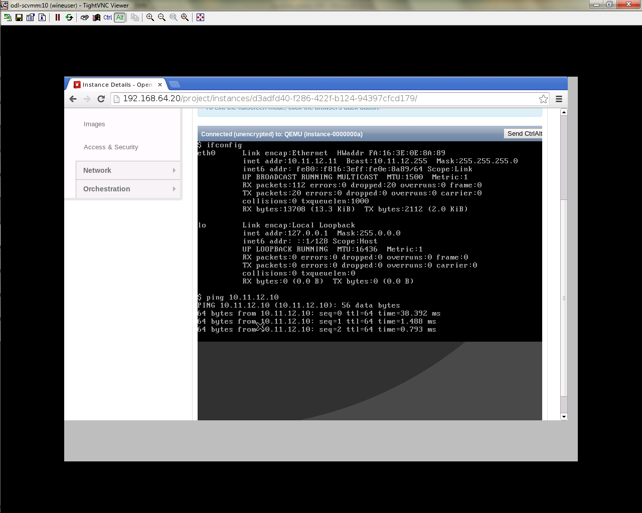
  • Login to the VM console and verify with a ping command.
Ping

Ping

Verification of Control and Compute Node after VM creation

  • Every time a new VM is created, more interfaces are added to the br-int bridge in Open vSwitch.
  • Use sudo ovs-vsctl show to list the number of interfaces added.
  • Please visit the DLUX GUI to list the new nodes in every switch.

Getting started with DLUX

Ensure that you have created a topology and enabled MD-SAL feature in the Karaf distribution before you use DLUX for network management.

Logging In

To log in to DLUX, after installing the application: * Open a browser and enter the login URL. If you have installed DLUX as a stand-alone, then the login URL is http://localhost:9000/DLUX/index.html. However if you have deployed DLUX with Karaf, then the login URL is http://<your IP>:8181/dlux/index.html. * Login to the application with user ID and password credentials as admin. NOTE:admin is the only user type available for DLUX in this release.

Working with DLUX

To get a complete DLUX feature list, install restconf, odl l2 switch, and switch while you start the DLUX distribution.

DLUX\_GUI

DLUX_GUI

Note

DLUX enables only those modules, whose APIs are responding. If you enable just the MD-SAL in beginning and then start dlux, only MD-SAL related tabs will be visible. While using the GUI if you enable AD-SAL karaf features, those tabs will appear automatically.

Viewing Network Statistics

The Nodes module on the left pane enables you to view the network statistics and port information for the switches in the network. * To use the Nodes module: ** Select Nodeson the left pane.

The right pane displays atable that lists all the nodes, node connectors and the statistics.
  • Enter a node ID in the Search Nodes tab to search by node connectors.
  • Click on the Node Connector number to view details such as port ID, port name, number of ports per switch, MAC Address, and so on.
  • Click Flows in the Statistics column to view Flow Table Statistics for the particular node like table ID, packet match, active flows and so on.
  • Click Node Connectors to view Node Connector Statistics for the particular node ID.

Viewing Network Topology

To view network topology: * Select Topology on the left pane. You will view the graphical representation on the right pane.

In the diagram
blue boxes represent the switches,black represents the hosts available, and lines represents how switches are connected.

Note

DLUX UI does not provide ability to add topology information. The Topology should be created using an open flow plugin. Controller stores this information in the database and displays on the DLUX page, when the you connect to the controller using OpenFlow.

Topology

Topology

OpenStack PackStack Installation Steps

VTN Manager Usage Examples

How to provision virtual L2 Network

Overview

This page explains how to provision virtual L2 network using VTN Manager. This page targets Boron release, so the procedure described here does not work in other releases.

Virtual L2 network for host1 and host3

Virtual L2 network for host1 and host3

Requirements

Mininet
mininet@mininet-vm:~$ sudo mn --controller=remote,ip=192.168.0.100 --topo tree,2

Note

Replace “192.168.0.100” with the IP address of OpenDaylight controller based on your environment.

  • you can check the topology that you have created by executing “net” command in the Mininet console.
mininet> net
h1 h1-eth0:s2-eth1
h2 h2-eth0:s2-eth2
h3 h3-eth0:s3-eth1
h4 h4-eth0:s3-eth2
s1 lo:  s1-eth1:s2-eth3 s1-eth2:s3-eth3
s2 lo:  s2-eth1:h1-eth0 s2-eth2:h2-eth0 s2-eth3:s1-eth1
s3 lo:  s3-eth1:h3-eth0 s3-eth2:h4-eth0 s3-eth3:s1-eth2
  • In this guide, you will provision the virtual L2 network to establish communication between h1 and h3.

Configuration

To provision the virtual L2 network for the two hosts (h1 and h3), execute REST API provided by VTN Manager as follows. It uses curl command to call the REST API.

curl --user "admin":"admin" -H "Content-type: application/json" -X POST http://localhost:8181/restconf/operations/vtn:update-vtn -d '{"input":{"tenant-name":"vtn1"}}'
curl --user "admin":"admin" -H "Content-type: application/json" -X POST http://localhost:8181/restconf/operations/vtn-vbridge:update-vbridge -d '{"input":{"tenant-name":"vtn1", "bridge-name":"vbr1"}}'
curl --user "admin":"admin" -H "Content-type: application/json" -X POST http://localhost:8181/restconf/operations/vtn-vinterface:update-vinterface -d '{"input":{"tenant-name":"vtn1", "bridge-name":"vbr1", "interface-name":"if1"}}'
curl --user "admin":"admin" -H "Content-type: application/json" -X POST http://localhost:8181/restconf/operations/vtn-vinterface:update-vinterface -d '{"input":{"tenant-name":"vtn1", "bridge-name":"vbr1", "interface-name":"if2"}}'
  • Configure two mappings on the created interfaces by executing the set-port-map RPC.
    • The interface if1 of the virtual bridge will be mapped to the port “s2-eth1” of the switch “openflow:2” of the Mininet.
      • The h1 is connected to the port “s2-eth1”.
    • The interface if2 of the virtual bridge will be mapped to the port “s3-eth1” of the switch “openflow:3” of the Mininet.
      • The h3 is connected to the port “s3-eth1”.
curl --user "admin":"admin" -H "Content-type: application/json" -X POST http://localhost:8181/restconf/operations/vtn-port-map:set-port-map -d '{"input":{"tenant-name":"vtn1", "bridge-name":"vbr1", "interface-name":"if1", "node":"openflow:2", "port-name":"s2-eth1"}}'
curl --user "admin":"admin" -H "Content-type: application/json" -X POST http://localhost:8181/restconf/operations/vtn-port-map:set-port-map -d '{"input":{"tenant-name":"vtn1", "bridge-name":"vbr1", "interface-name":"if2", "node":"openflow:3", "port-name":"s3-eth1"}}'

Verification

  • Please execute ping from h1 to h3 to verify if the virtual L2 network for h1 and h3 is provisioned successfully.
mininet> h1 ping h3
PING 10.0.0.3 (10.0.0.3) 56(84) bytes of data.
64 bytes from 10.0.0.3: icmp_seq=1 ttl=64 time=243 ms
64 bytes from 10.0.0.3: icmp_seq=2 ttl=64 time=0.341 ms
64 bytes from 10.0.0.3: icmp_seq=3 ttl=64 time=0.078 ms
64 bytes from 10.0.0.3: icmp_seq=4 ttl=64 time=0.079 ms
  • You can also verify the configuration by executing the following REST API. It shows all configuration in VTN Manager.
curl --user "admin":"admin" -H "Content-type: application/json" -X GET http://localhost:8181/restconf/operational/vtn:vtns/
  • The result of the command should be like this.
{
  "vtns": {
    "vtn": [
    {
      "name": "vtn1",
        "vtenant-config": {
          "idle-timeout": 300,
          "hard-timeout": 0
        },
        "vbridge": [
        {
          "name": "vbr1",
          "bridge-status": {
            "state": "UP",
            "path-faults": 0
          },
          "vbridge-config": {
            "age-interval": 600
          },
          "vinterface": [
          {
            "name": "if2",
            "vinterface-status": {
              "entity-state": "UP",
              "state": "UP",
              "mapped-port": "openflow:3:3"
            },
            "vinterface-config": {
              "enabled": true
            },
            "port-map-config": {
              "vlan-id": 0,
              "port-name": "s3-eth1",
              "node": "openflow:3"
            }
          },
          {
            "name": "if1",
            "vinterface-status": {
              "entity-state": "UP",
              "state": "UP",
              "mapped-port": "openflow:2:1"
            },
            "vinterface-config": {
              "enabled": true
            },
            "port-map-config": {
              "vlan-id": 0,
              "port-name": "s2-eth1",
              "node": "openflow:2"
            }
          }
          ]
        }
      ]
    }
    ]
  }
}

Cleaning Up

curl --user "admin":"admin" -H "Content-type: application/json" -X POST http://localhost:8181/restconf/operations/vtn:remove-vtn -d '{"input":{"tenant-name":"vtn1"}}'

How To Test Vlan-Map In Mininet Environment

Overview

This page explains how to test Vlan-map in a multi host scenario using mininet. This page targets Boron release, so the procedure described here does not work in other releases.

Example that demonstrates vlanmap testing in Mininet Environment

Example that demonstrates vlanmap testing in Mininet Environment

Requirements

Save the mininet script given below as vlan_vtn_test.py and run the mininet script in the mininet environment where Mininet is installed.

Mininet Script

https://wiki.opendaylight.org/view/OpenDaylight_Virtual_Tenant_Network_(VTN):Scripts:Mininet#Network_with_hosts_in_different_vlan

  • Run the mininet script
sudo mn --controller=remote,ip=192.168.64.13 --custom vlan_vtn_test.py --topo mytopo

Note

Replace “192.168.64.13” with the IP address of OpenDaylight controller based on your environment.

  • You can check the topology that you have created by executing “net” command in the Mininet console.
mininet> net
h1 h1-eth0.200:s1-eth1
h2 h2-eth0.300:s2-eth2
h3 h3-eth0.200:s2-eth3
h4 h4-eth0.300:s2-eth4
h5 h5-eth0.200:s3-eth2
h6 h6-eth0.300:s3-eth3
s1 lo:  s1-eth1:h1-eth0.200 s1-eth2:s2-eth1 s1-eth3:s3-eth1
s2 lo:  s2-eth1:s1-eth2 s2-eth2:h2-eth0.300 s2-eth3:h3-eth0.200 s2-eth4:h4-eth0.300
s3 lo:  s3-eth1:s1-eth3 s3-eth2:h5-eth0.200 s3-eth3:h6-eth0.300
c0

Configuration

To test vlan-map, execute REST API provided by VTN Manager as follows.

curl --user "admin":"admin" -H "Content-type: application/json" -X POST http://localhost:8181/restconf/operations/vtn:update-vtn -d '{"input":{"tenant-name":"vtn1"}}'
curl --user "admin":"admin" -H "Content-type: application/json" -X POST http://localhost:8181/restconf/operations/vtn-vbridge:update-vbridge -d '{"input":{"tenant-name":"vtn1","bridge-name":"vbr1"}}'
curl --user "admin":"admin" -H "Content-type: application/json" -X POST http://localhost:8181/restconf/operations/vtn-vlan-map:add-vlan-map -d '{"input":{"vlan-id":200,"tenant-name":"vtn1","bridge-name":"vbr1"}}'
curl --user "admin":"admin" -H "Content-type: application/json" -X POST http://localhost:8181/restconf/operations/vtn-vbridge:update-vbridge -d '{"input":{"tenant-name":"vtn1","bridge-name":"vbr2"}}'
curl --user "admin":"admin" -H "Content-type: application/json" -X POST http://localhost:8181/restconf/operations/vtn-vlan-map:add-vlan-map -d '{"input":{"vlan-id":300,"tenant-name":"vtn1","bridge-name":"vbr2"}}'

Verification

  • Please execute pingall in mininet environment to view the host reachability.
mininet> pingall
Ping: testing ping reachability
h1 -> X h3 X h5 X
h2 -> X X h4 X h6
h3 -> h1 X X h5 X
h4 -> X h2 X X h6
h5 -> h1 X h3 X X
h6 -> X h2 X h4 X
  • You can also verify the configuration by executing the following REST API. It shows all configurations in VTN Manager.
curl --user "admin":"admin" -H "Content-type: application/json" -X GET http://localhost:8181/restconf/operational/vtn:vtns
  • The result of the command should be like this.
{
  "vtns": {
    "vtn": [
    {
      "name": "vtn1",
        "vtenant-config": {
          "hard-timeout": 0,
          "idle-timeout": 300,
          "description": "creating vtn"
        },
        "vbridge": [
        {
          "name": "vbr2",
          "vbridge-config": {
            "age-interval": 600,
            "description": "creating vbr2"
          },
          "bridge-status": {
            "state": "UP",
            "path-faults": 0
          },
          "vlan-map": [
          {
            "map-id": "ANY.300",
            "vlan-map-config": {
              "vlan-id": 300
            },
            "vlan-map-status": {
              "active": true
            }
          }
          ]
        },
        {
          "name": "vbr1",
          "vbridge-config": {
            "age-interval": 600,
            "description": "creating vbr1"
          },
          "bridge-status": {
            "state": "UP",
            "path-faults": 0
          },
          "vlan-map": [
          {
            "map-id": "ANY.200",
            "vlan-map-config": {
              "vlan-id": 200
            },
            "vlan-map-status": {
              "active": true
            }
          }
          ]
        }
      ]
    }
    ]
  }
}

Cleaning Up

curl --user "admin":"admin" -H "Content-type: application/json" -X POST http://localhost:8181/restconf/operations/vtn:remove-vtn -d '{"input":{"tenant-name":"vtn1"}}'

How To Configure Service Function Chaining using VTN Manager

Overview

This page explains how to configure VTN Manager for Service Chaining. This page targets Boron release, so the procedure described here does not work in other releases.

Service Chaining With One Service

Service Chaining With One Service

Requirements

  • Please refer to the Installation Pages to run ODL with VTN Feature enabled.
  • Please ensure Bridge-Utils package is installed in mininet environment before running the mininet script.
  • To install Bridge-Utils package run sudo apt-get install bridge-utils (assuming Ubuntu is used to run mininet, If not then this is not required).
  • Save the mininet script given below as topo_handson.py and run the mininet script in the mininet environment where Mininet is installed.

Mininet Script

sudo mn --controller=remote,ip=<Controller IP> --custom <path>\topo_handson.py --topo mytopo2
mininet> net
h11 h11-eth0:s1-eth1
h12 h12-eth0:s1-eth2
h21 h21-eth0:s2-eth1
h22 h22-eth0:s2-eth2
h23 h23-eth0:s2-eth3
srvc1 srvc1-eth0:s3-eth3 srvc1-eth1:s4-eth3
srvc2 srvc2-eth0:s3-eth4 srvc2-eth1:s4-eth4
s1 lo:  s1-eth1:h11-eth0 s1-eth2:h12-eth0 s1-eth3:s2-eth4 s1-eth4:s3-eth2
s2 lo:  s2-eth1:h21-eth0 s2-eth2:h22-eth0 s2-eth3:h23-eth0 s2-eth4:s1-eth3 s2-eth5:s4-eth1
s3 lo:  s3-eth1:s4-eth2 s3-eth2:s1-eth4 s3-eth3:srvc1-eth0 s3-eth4:srvc2-eth0
s4 lo:  s4-eth1:s2-eth5 s4-eth2:s3-eth1 s4-eth3:srvc1-eth1 s4-eth4:srvc2-eth1

Configurations

Mininet
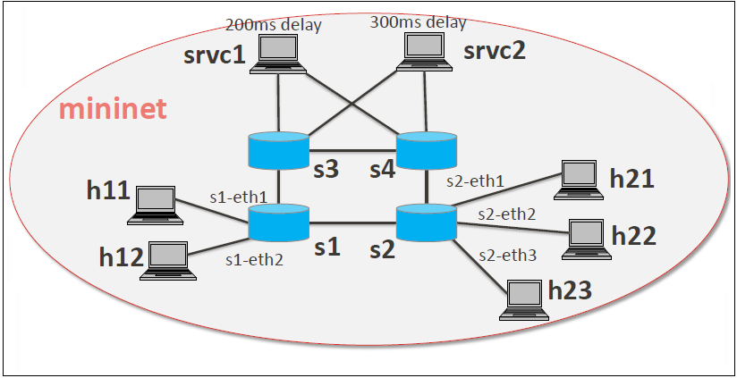
  • Please follow the below steps to configure the network in mininet as in the below image:
Mininet Configuration

Mininet Configuration

Configure service nodes
  • Please execute the following commands in the mininet console where mininet script is executed.
mininet> srvc1 ip addr del 10.0.0.6/8 dev srvc1-eth0
mininet> srvc1 brctl addbr br0
mininet> srvc1 brctl addif br0 srvc1-eth0
mininet> srvc1 brctl addif br0 srvc1-eth1
mininet> srvc1 ifconfig br0 up
mininet> srvc1 tc qdisc add dev srvc1-eth1 root netem delay 200ms
mininet> srvc2 ip addr del 10.0.0.7/8 dev srvc2-eth0
mininet> srvc2 brctl addbr br0
mininet> srvc2 brctl addif br0 srvc2-eth0
mininet> srvc2 brctl addif br0 srvc2-eth1
mininet> srvc2 ifconfig br0 up
mininet> srvc2 tc qdisc add dev srvc2-eth1 root netem delay 300ms

Controller

Multi-Tenancy
  • Please execute the below commands to configure the network topology in the controller as in the below image:
Tenant2

Tenant2

Please execute the below commands in controller

Note

The below commands are for the difference in behavior of Manager in Boron topology. The Link below has the details for this bug: https://bugs.opendaylight.org/show_bug.cgi?id=3818.

curl --user admin:admin -H 'content-type: application/json' -H 'ipaddr:127.0.0.1' -X PUT http://localhost:8181/restconf/config/vtn-static-topology:vtn-static-topology/static-edge-ports -d '{"static-edge-ports": {"static-edge-port": [ {"port": "openflow:3:3"}, {"port": "openflow:3:4"}, {"port": "openflow:4:3"}, {"port": "openflow:4:4"}]}}'
curl --user "admin":"admin" -H "Content-type: application/json" -X POST http://localhost:8181/restconf/operations/vtn:update-vtn -d '{"input":{"tenant-name":"vtn1","update-mode":"CREATE","operation":"SET","description":"creating vtn","idle-timeout":300,"hard-timeout":0}}'
curl --user "admin":"admin" -H "Content-type: application/json" -X POST http://localhost:8181/restconf/operations/vtn-vbridge:update-vbridge -d '{"input":{"update-mode":"CREATE","operation":"SET","description":"creating vbr","tenant-name":"vtn1","bridge-name":"vbr1"}}'
curl --user "admin":"admin" -H "Content-type: application/json" -X POST http://localhost:8181/restconf/operations/vtn-vinterface:update-vinterface -d '{"input":{"update-mode":"CREATE","operation":"SET","description":"Creating vbrif1 interface","tenant-name":"vtn1","bridge-name":"vbr1","interface-name":"if1"}}'
  • Configure port mapping on the interface by executing the set-port-map RPC.
    • The interface if1 of the virtual bridge will be mapped to the port “s1-eth2” of the switch “openflow:1” of the Mininet.
      • The h12 is connected to the port “s1-eth2”.
curl --user "admin":"admin" -H "Content-type: application/json" -X POST http://localhost:8181/restconf/operations/vtn-port-map:set-port-map -d '{"input":{"vlan-id":0,"tenant-name":"vtn1","bridge-name":"vbr1","interface-name":"if1","node":"openflow:1","port-name":"s1-eth2"}}'
curl --user "admin":"admin" -H "Content-type: application/json" -X POST http://localhost:8181/restconf/operations/vtn-vinterface:update-vinterface -d '{"input":{"update-mode":"CREATE","operation":"SET","description":"Creating vbrif2 interface","tenant-name":"vtn1","bridge-name":"vbr1","interface-name":"if2"}}'
  • Configure port mapping on the interface by executing the set-port-map RPC.
    • The interface if2 of the virtual bridge will be mapped to the port “s2-eth2” of the switch “openflow:2” of the Mininet.
      • The h22 is connected to the port “s2-eth2”.
curl --user "admin":"admin" -H "Content-type: application/json" -X POST http://localhost:8181/restconf/operations/vtn-port-map:set-port-map -d '{"input":{"vlan-id":0,"tenant-name":"vtn1","bridge-name":"vbr1","interface-name":"if2","node":"openflow:2","port-name":"s2-eth2"}}'
curl --user "admin":"admin" -H "Content-type: application/json" -X POST http://localhost:8181/restconf/operations/vtn-vinterface:update-vinterface -d '{"input":{"update-mode":"CREATE","operation":"SET","description":"Creating vbrif3 interface","tenant-name":"vtn1","bridge-name":"vbr1","interface-name":"if3"}}'
  • Configure port mapping on the interfaces by executing the set-port-map RPC.
    • The interface if3 of the virtual bridge will be mapped to the port “s2-eth3” of the switch “openflow:2” of the Mininet.
      • The h23 is connected to the port “s2-eth3”.
curl --user "admin":"admin" -H "Content-type: application/json" -X POST http://localhost:8181/restconf/operations/vtn-port-map:set-port-map -d '{"input":{"vlan-id":0,"tenant-name":"vtn1","bridge-name":"vbr1","interface-name":"if3","node":"openflow:2","port-name":"s2-eth3"}}'

Traffic filtering

  • Create flowcondition named cond_1 by executing the set-flow-condition RPC.
    • For option source and destination-network, get inet address of host h12(src) and h22(dst) from mininet.
curl --user "admin":"admin" -H "Content-type: application/json" -X POST http://localhost:8181/restconf/operations/vtn-flow-condition:set-flow-condition -d '{"input":{"operation":"SET","present":"false","name":"cond_1","vtn-flow-match":[{"index":1,"vtn-ether-match":{},"vtn-inet-match":{"source-network":"10.0.0.2/32","destination-network":"10.0.0.4/32"}}]}}'
  • Flow filter demonstration with DROP action-type. Create Flowfilter in VBR Interface if1 by executing the set-flow-filter RPC.
curl --user "admin":"admin" -H "Content-type: application/json" -X POST http://localhost:8181/restconf/operations/vtn-flow-filter:set-flow-filter -d '{"input":{"output":"false","tenant-name":"vtn1","bridge-name":"vbr1","interface-name":"if1","vtn-flow-filter":[{"condition":"cond_1","index":10,"vtn-drop-filter":{}}]}}'

Service Chaining

With One Service
  • Please execute the below commands to configure the network topology which sends some specific traffic via a single service(External device) in the controller as in the below image:
Service Chaining With One Service LLD

Service Chaining With One Service LLD

curl --user "admin":"admin" -H "Content-type: application/json" -X POST http://localhost:8181/restconf/operations/vtn-vterminal:update-vterminal -d '{"input":{"update-mode":"CREATE","operation":"SET","tenant-name":"vtn1","terminal-name":"vt_srvc1_1","description":"Creating vterminal"}}'
curl --user "admin":"admin" -H "Content-type: application/json" -X POST http://localhost:8181/restconf/operations/vtn-vinterface:update-vinterface -d '{"input":{"update-mode":"CREATE","operation":"SET","description":"Creating vterminal IF","enabled":"true","tenant-name":"vtn1","terminal-name":"vt_srvc1_1","interface-name":"IF"}}'
  • Configure port mapping on the interfaces by executing the set-port-map RPC.
    • The interface IF of the virtual terminal will be mapped to the port “s3-eth3” of the switch “openflow:3” of the Mininet.
      • The h12 is connected to the port “s3-eth3”.
curl --user "admin":"admin" -H "Content-type: application/json" -X POST http://localhost:8181/restconf/operations/vtn-port-map:set-port-map -d '{"input":{"tenant-name":"vtn1","terminal-name":"vt_srvc1_1","interface-name":"IF","node":"openflow:3","port-name":"s3-eth3"}}'
curl --user "admin":"admin" -H "Content-type: application/json" -X POST http://localhost:8181/restconf/operations/vtn-vterminal:update-vterminal -d '{"input":{"update-mode":"CREATE","operation":"SET","tenant-name":"vtn1","terminal-name":"vt_srvc1_2","description":"Creating vterminal"}}'
curl --user "admin":"admin" -H "Content-type: application/json" -X POST http://localhost:8181/restconf/operations/vtn-vinterface:update-vinterface -d '{"input":{"update-mode":"CREATE","operation":"SET","description":"Creating vterminal IF","enabled":"true","tenant-name":"vtn1","terminal-name":"vt_srvc1_2","interface-name":"IF"}}'
  • Configure port mapping on the interfaces by executing the set-port-map RPC.
    • The interface IF of the virtual terminal will be mapped to the port “s4-eth3” of the switch “openflow:4” of the Mininet.
      • The h22 is connected to the port “s4-eth3”.
curl --user "admin":"admin" -H "Content-type: application/json" -X POST http://localhost:8181/restconf/operations/vtn-port-map:set-port-map -d '{"input":{"tenant-name":"vtn1","terminal-name":"vt_srvc1_2","interface-name":"IF","node":"openflow:4","port-name":"s4-eth3"}}'
  • Create flowcondition named cond_1 by executing the set-flow-condition RPC.
    • For option source and destination-network, get inet address of host h12(src) and h22(dst) from mininet.
curl --user "admin":"admin" -H "Content-type: application/json" -X POST http://localhost:8181/restconf/operations/vtn-flow-condition:set-flow-condition -d '{"input":{"operation":"SET","present":"false","name":"cond_1","vtn-flow-match":[{"index":1,"vtn-ether-match":{},"vtn-inet-match":{"source-network":"10.0.0.2/32","destination-network":"10.0.0.4/32"}}]}}'
curl --user "admin":"admin" -H "Content-type: application/json" -X POST http://localhost:8181/restconf/operations/vtn-flow-condition:set-flow-condition -d '{"input":{"operation":"SET","present":"false","name":"cond_any","vtn-flow-match":[{"index":1}]}}'
  • Flow filter demonstration with redirect action-type. Create Flowfilter in virtual terminal vt_srvc1_2 interface IF by executing the set-flow-filter RPC.
    • Flowfilter redirects vt_srvc1_2 to bridge1-IF2
curl --user "admin":"admin" -H "Content-type: application/json" -X POST http://localhost:8181/restconf/operations/vtn-flow-filter:set-flow-filter -d '{"input":{"output":"false","tenant-name":"vtn1","terminal-name":"vt_srvc1_2","interface-name":"IF","vtn-flow-filter":[{"condition":"cond_any","index":10,"vtn-redirect-filter":{"redirect-destination":{"bridge-name":"vbr1","interface-name":"if2"},"output":"true"}}]}}'
  • Flow filter demonstration with redirect action-type. Create Flowfilter in vbridge vbr1 interface if1 by executing the set-flow-filter RPC.
    • Flow filter redirects Bridge1-IF1 to vt_srvc1_1
curl --user "admin":"admin" -H "Content-type: application/json" -X POST http://localhost:8181/restconf/operations/vtn-flow-filter:set-flow-filter -d '{"input":{"output":"false","tenant-name":"vtn1","bridge-name":"vbr1","interface-name":"if1","vtn-flow-filter":[{"condition":"cond_1","index":10,"vtn-redirect-filter":{"redirect-destination":{"terminal-name":"vt_srvc1_1","interface-name":"IF"},"output":"true"}}]}}'

Verification

Service Chaining With One Service

Service Chaining With One Service

  • Ping host12 to host22 to view the host rechability, a delay of 200ms will be taken to reach host22 as below.
mininet> h12 ping h22
PING 10.0.0.4 (10.0.0.4) 56(84) bytes of data.
64 bytes from 10.0.0.4: icmp_seq=35 ttl=64 time=209 ms
64 bytes from 10.0.0.4: icmp_seq=36 ttl=64 time=201 ms
64 bytes from 10.0.0.4: icmp_seq=37 ttl=64 time=200 ms
64 bytes from 10.0.0.4: icmp_seq=38 ttl=64 time=200 ms
With two services
  • Please execute the below commands to configure the network topology which sends some specific traffic via two services(External device) in the controller as in the below image.
Service Chaining With Two Services LLD

Service Chaining With Two Services LLD

curl --user "admin":"admin" -H "Content-type: application/json" -X POST http://localhost:8181/restconf/operations/vtn-vterminal:update-vterminal -d '{"input":{"update-mode":"CREATE","operation":"SET","tenant-name":"vtn1","terminal-name":"vt_srvc2_1","description":"Creating vterminal"}}'
curl --user "admin":"admin" -H "Content-type: application/json" -X POST http://localhost:8181/restconf/operations/vtn-vinterface:update-vinterface -d '{"input":{"update-mode":"CREATE","operation":"SET","description":"Creating vterminal IF","enabled":"true","tenant-name":"vtn1","terminal-name":"vt_srvc2_1","interface-name":"IF"}}'
  • Configure port mapping on the interfaces by executing the set-port-map RPC.
    • The interface IF of the virtual terminal will be mapped to the port “s3-eth4” of the switch “openflow:3” of the Mininet.
      • The host h12 is connected to the port “s3-eth4”.
curl --user "admin":"admin" -H "Content-type: application/json" -X POST http://localhost:8181/restconf/operations/vtn-port-map:set-port-map -d '{"input":{"tenant-name":"vtn1","terminal-name":"vt_srvc2_1","interface-name":"IF","node":"openflow:3","port-name":"s3-eth4"}}'
curl --user "admin":"admin" -H "Content-type: application/json" -X POST http://localhost:8181/restconf/operations/vtn-vterminal:update-vterminal -d '{"input":{"update-mode":"CREATE","operation":"SET","tenant-name":"vtn1","terminal-name":"vt_srvc2_2","description":"Creating vterminal"}}'
curl --user "admin":"admin" -H "Content-type: application/json" -X POST http://localhost:8181/restconf/operations/vtn-vinterface:update-vinterface -d '{"input":{"update-mode":"CREATE","operation":"SET","description":"Creating vterminal IF","enabled":"true","tenant-name":"vtn1","terminal-name":"vt_srvc2_2","interface-name":"IF"}}'
  • Configure port mapping on the interfaces by executing the set-port-map RPC.
    • The interface IF of the virtual terminal will be mapped to the port “s4-eth4” of the switch “openflow:4” of the mininet.
      • The host h22 is connected to the port “s4-eth4”.
curl --user "admin":"admin" -H "Content-type: application/json" -X POST http://localhost:8181/restconf/operations/vtn-port-map:set-port-map -d '{"input":{"tenant-name":"vtn1","terminal-name":"vt_srvc2_2","interface-name":"IF","node":"openflow:4","port-name":"s4-eth4"}}'
  • Flow filter demonstration with redirect action-type. Create Flowfilter in virtual terminal vt_srvc2_2 interface IF by executing the set-flow-filter RPC.
    • Flow filter redirects vt_srvc2_2 to Bridge1-IF2.
curl --user "admin":"admin" -H "Content-type: application/json" -X POST http://localhost:8181/restconf/operations/vtn-flow-filter:set-flow-filter -d '{"input":{"output":"false","tenant-name":"vtn1","terminal-name":"vt_srvc2_2","interface-name":"IF","vtn-flow-filter":[{"condition":"cond_any","index":10,"vtn-redirect-filter":{"redirect-destination":{"bridge-name":"vbr1","interface-name":"if2"},"output":"true"}}]}}'
  • Flow filter demonstration with redirect action-type. Create Flowfilter in virtual terminal vt_srvc2_2 interface IF by executing the set-flow-filter RPC.
    • Flow filter redirects vt_srvc1_2 to vt_srvc2_1.
curl --user "admin":"admin" -H "Content-type: application/json" -X POST http://localhost:8181/restconf/operations/vtn-flow-filter:set-flow-filter -d '{"input":{"output":"false","tenant-name":"vtn1","terminal-name":"vt_srvc1_2","interface-name":"IF","vtn-flow-filter":[{"condition":"cond_any","index":10,"vtn-redirect-filter":{"redirect-destination":{"terminal-name":"vt_srvc2_1","interface-name":"IF"},"output":"true"}}]}}'

Verification

Service Chaining With Two Service

Service Chaining With Two Service

  • Ping host12 to host22 to view the host rechability, a delay of 500ms will be taken to reach host22 as below.
mininet> h12 ping h22
PING 10.0.0.4 (10.0.0.4) 56(84) bytes of data.
64 bytes from 10.0.0.4: icmp_seq=1 ttl=64 time=512 ms
64 bytes from 10.0.0.4: icmp_seq=2 ttl=64 time=501 ms
64 bytes from 10.0.0.4: icmp_seq=3 ttl=64 time=500 ms
64 bytes from 10.0.0.4: icmp_seq=4 ttl=64 time=500 ms
  • You can verify the configuration by executing the following REST API. It shows all configuration in VTN Manager.
curl --user "admin":"admin" -H "Content-type: application/json" -X GET http://localhost:8181/restconf/operational/vtn:vtns
{
  "vtn": [
  {
    "name": "vtn1",
      "vtenant-config": {
        "hard-timeout": 0,
        "idle-timeout": 300,
        "description": "creating vtn"
      },
      "vbridge": [
      {
        "name": "vbr1",
        "vbridge-config": {
          "age-interval": 600,
          "description": "creating vbr"
        },
        "bridge-status": {
          "state": "UP",
          "path-faults": 0
        },
        "vinterface": [
        {
          "name": "if1",
          "vinterface-status": {
            "mapped-port": "openflow:1:2",
            "state": "UP",
            "entity-state": "UP"
          },
          "port-map-config": {
            "vlan-id": 0,
            "node": "openflow:1",
            "port-name": "s1-eth2"
          },
          "vinterface-config": {
            "description": "Creating vbrif1 interface",
            "enabled": true
          },
          "vinterface-input-filter": {
            "vtn-flow-filter": [
            {
              "index": 10,
              "condition": "cond_1",
              "vtn-redirect-filter": {
                "output": true,
                "redirect-destination": {
                  "terminal-name": "vt_srvc1_1",
                  "interface-name": "IF"
                }
              }
            }
            ]
          }
        },
        {
          "name": "if2",
          "vinterface-status": {
            "mapped-port": "openflow:2:2",
            "state": "UP",
            "entity-state": "UP"
          },
          "port-map-config": {
            "vlan-id": 0,
            "node": "openflow:2",
            "port-name": "s2-eth2"
          },
          "vinterface-config": {
            "description": "Creating vbrif2 interface",
            "enabled": true
          }
        },
        {
          "name": "if3",
          "vinterface-status": {
            "mapped-port": "openflow:2:3",
            "state": "UP",
            "entity-state": "UP"
          },
          "port-map-config": {
            "vlan-id": 0,
            "node": "openflow:2",
            "port-name": "s2-eth3"
          },
          "vinterface-config": {
            "description": "Creating vbrif3 interface",
            "enabled": true
          }
        }
        ]
      }
    ],
      "vterminal": [
      {
        "name": "vt_srvc2_2",
        "bridge-status": {
          "state": "UP",
          "path-faults": 0
        },
        "vinterface": [
        {
          "name": "IF",
          "vinterface-status": {
            "mapped-port": "openflow:4:4",
            "state": "UP",
            "entity-state": "UP"
          },
          "port-map-config": {
            "vlan-id": 0,
            "node": "openflow:4",
            "port-name": "s4-eth4"
          },
          "vinterface-config": {
            "description": "Creating vterminal IF",
            "enabled": true
          },
          "vinterface-input-filter": {
            "vtn-flow-filter": [
            {
              "index": 10,
              "condition": "cond_any",
              "vtn-redirect-filter": {
                "output": true,
                "redirect-destination": {
                  "bridge-name": "vbr1",
                  "interface-name": "if2"
                }
              }
            }
            ]
          }
        }
        ],
          "vterminal-config": {
            "description": "Creating vterminal"
          }
      },
      {
        "name": "vt_srvc1_1",
        "bridge-status": {
          "state": "UP",
          "path-faults": 0
        },
        "vinterface": [
        {
          "name": "IF",
          "vinterface-status": {
            "mapped-port": "openflow:3:3",
            "state": "UP",
            "entity-state": "UP"
          },
          "port-map-config": {
            "vlan-id": 0,
            "node": "openflow:3",
            "port-name": "s3-eth3"
          },
          "vinterface-config": {
            "description": "Creating vterminal IF",
            "enabled": true
          }
        }
        ],
          "vterminal-config": {
            "description": "Creating vterminal"
          }
      },
      {
        "name": "vt_srvc1_2",
        "bridge-status": {
          "state": "UP",
          "path-faults": 0
        },
        "vinterface": [
        {
          "name": "IF",
          "vinterface-status": {
            "mapped-port": "openflow:4:3",
            "state": "UP",
            "entity-state": "UP"
          },
          "port-map-config": {
            "vlan-id": 0,
            "node": "openflow:4",
            "port-name": "s4-eth3"
          },
          "vinterface-config": {
            "description": "Creating vterminal IF",
            "enabled": true
          },
          "vinterface-input-filter": {
            "vtn-flow-filter": [
            {
              "index": 10,
              "condition": "cond_any",
              "vtn-redirect-filter": {
                "output": true,
                "redirect-destination": {
                  "terminal-name": "vt_srvc2_1",
                  "interface-name": "IF"
                }
              }
            }
            ]
          }
        }
        ],
          "vterminal-config": {
            "description": "Creating vterminal"
          }
      },
      {
        "name": "vt_srvc2_1",
        "bridge-status": {
          "state": "UP",
          "path-faults": 0
        },
        "vinterface": [
        {
          "name": "IF",
          "vinterface-status": {
            "mapped-port": "openflow:3:4",
            "state": "UP",
            "entity-state": "UP"
          },
          "port-map-config": {
            "vlan-id": 0,
            "node": "openflow:3",
            "port-name": "s3-eth4"
          },
          "vinterface-config": {
            "description": "Creating vterminal IF",
            "enabled": true
          }
        }
        ],
          "vterminal-config": {
            "description": "Creating vterminal"
          }
      }
    ]
  }
  ]
}

Cleaning Up

  • To clean up both VTN and flowconditions.
  • You can delete the virtual tenant vtn1 by executing the remove-vtn RPC.
curl --user "admin":"admin" -H "Content-type: application/json" -X POST http://localhost:8181/restconf/operations/vtn:remove-vtn -d '{"input":{"tenant-name":"vtn1"}}'
curl --user "admin":"admin" -H "Content-type: application/json" -X POST http://localhost:8181/restconf/operations/vtn-flow-condition:remove-flow-condition -d '{"input":{"name":"cond_1"}}'
curl --user "admin":"admin" -H "Content-type: application/json" -X POST http://localhost:8181/restconf/operations/vtn-flow-condition:remove-flow-condition -d '{"input":{"name":"cond_any"}}'

How To View Dataflows

Overview

This page explains how to view Dataflows using VTN Manager. This page targets Boron release, so the procedure described here does not work in other releases.

Dataflow feature enables retrieval and display of data flows in the OpenFlow network. The data flows can be retrieved based on an OpenFlow switch or a switch port or a L2 source host.

The flow information provided by this feature are

  • Location of virtual node which maps the incoming packet and outgoing packets.
  • Location of physical switch port where incoming and outgoing packets is sent and received.
  • A sequence of physical route info which represents the packet route in the physical network.

Configuration

Verification

After creating vlan mapping configuration from the above page, execute as below in mininet to get switch details.

mininet> net
h1 h1-eth0.200:s1-eth1
h2 h2-eth0.300:s2-eth2
h3 h3-eth0.200:s2-eth3
h4 h4-eth0.300:s2-eth4
h5 h5-eth0.200:s3-eth2
h6 h6-eth0.300:s3-eth3
s1 lo:  s1-eth1:h1-eth0.200 s1-eth2:s2-eth1 s1-eth3:s3-eth1
s2 lo:  s2-eth1:s1-eth2 s2-eth2:h2-eth0.300 s2-eth3:h3-eth0.200 s2-eth4:h4-eth0.300
s3 lo:  s3-eth1:s1-eth3 s3-eth2:h5-eth0.200 s3-eth3:h6-eth0.300
c0
mininet>

Please execute ping from h1 to h3 to check hosts reachability.

mininet> h1 ping h3
PING 10.0.0.3 (10.0.0.3) 56(84) bytes of data.
64 bytes from 10.0.0.3: icmp_seq=1 ttl=64 time=11.4 ms
64 bytes from 10.0.0.3: icmp_seq=2 ttl=64 time=0.654 ms
64 bytes from 10.0.0.3: icmp_seq=3 ttl=64 time=0.093 ms

Parallely execute below Restconf command to get data flow information of node “openflow:1” and its port “s1-eth1”.

curl --user "admin":"admin" -H "Content-type: application/json" -X POST http://localhost:8181/restconf/operations/vtn-flow:get-data-flow -d '{"input":{"tenant-name":"vtn1","mode":"DETAIL","node":"openflow:1","data-flow-port":{"port-id":"1","port-name":"s1-eth1"}}}'
{
  "output": {
    "data-flow-info": [
    {
      "averaged-data-flow-stats": {
        "packet-count": 1.1998800119988002,
          "start-time": 1455241209151,
          "end-time": 1455241219152,
          "byte-count": 117.58824117588242
      },
        "physical-route": [
        {
          "physical-ingress-port": {
            "port-name": "s2-eth3",
            "port-id": "3"
          },
          "physical-egress-port": {
            "port-name": "s2-eth1",
            "port-id": "1"
          },
          "node": "openflow:2",
          "order": 0
        },
        {
          "physical-ingress-port": {
            "port-name": "s1-eth2",
            "port-id": "2"
          },
          "physical-egress-port": {
            "port-name": "s1-eth1",
            "port-id": "1"
          },
          "node": "openflow:1",
          "order": 1
        }
      ],
        "data-egress-node": {
          "bridge-name": "vbr1",
          "tenant-name": "vtn1"
        },
        "hard-timeout": 0,
        "idle-timeout": 300,
        "data-flow-stats": {
          "duration": {
            "nanosecond": 640000000,
            "second": 362
          },
          "packet-count": 134,
          "byte-count": 12932
        },
        "data-egress-port": {
          "node": "openflow:1",
          "port-name": "s1-eth1",
          "port-id": "1"
        },
        "data-ingress-node": {
          "bridge-name": "vbr1",
          "tenant-name": "vtn1"
        },
        "data-ingress-port": {
          "node": "openflow:2",
          "port-name": "s2-eth3",
          "port-id": "3"
        },
        "creation-time": 1455240855753,
        "data-flow-match": {
          "vtn-ether-match": {
            "vlan-id": 200,
            "source-address": "6a:ff:e2:81:86:bb",
            "destination-address": "26:9f:82:70:ec:66"
          }
        },
        "virtual-route": [
        {
          "reason": "VLANMAPPED",
          "virtual-node-path": {
            "bridge-name": "vbr1",
            "tenant-name": "vtn1"
          },
          "order": 0
        },
        {
          "reason": "FORWARDED",
          "virtual-node-path": {
            "bridge-name": "vbr1",
            "tenant-name": "vtn1"
          },
          "order": 1
        }
      ],
        "flow-id": 16
    },
    {
      "averaged-data-flow-stats": {
        "packet-count": 1.1998800119988002,
        "start-time": 1455241209151,
        "end-time": 1455241219152,
        "byte-count": 117.58824117588242
      },
      "physical-route": [
      {
        "physical-ingress-port": {
          "port-name": "s1-eth1",
          "port-id": "1"
        },
        "physical-egress-port": {
          "port-name": "s1-eth2",
          "port-id": "2"
        },
        "node": "openflow:1",
        "order": 0
      },
      {
        "physical-ingress-port": {
          "port-name": "s2-eth1",
          "port-id": "1"
        },
        "physical-egress-port": {
          "port-name": "s2-eth3",
          "port-id": "3"
        },
        "node": "openflow:2",
        "order": 1
      }
      ],
        "data-egress-node": {
          "bridge-name": "vbr1",
          "tenant-name": "vtn1"
        },
        "hard-timeout": 0,
        "idle-timeout": 300,
        "data-flow-stats": {
          "duration": {
            "nanosecond": 587000000,
            "second": 362
          },
          "packet-count": 134,
          "byte-count": 12932
        },
        "data-egress-port": {
          "node": "openflow:2",
          "port-name": "s2-eth3",
          "port-id": "3"
        },
        "data-ingress-node": {
          "bridge-name": "vbr1",
          "tenant-name": "vtn1"
        },
        "data-ingress-port": {
          "node": "openflow:1",
          "port-name": "s1-eth1",
          "port-id": "1"
        },
        "creation-time": 1455240855747,
        "data-flow-match": {
          "vtn-ether-match": {
            "vlan-id": 200,
            "source-address": "26:9f:82:70:ec:66",
            "destination-address": "6a:ff:e2:81:86:bb"
          }
        },
        "virtual-route": [
        {
          "reason": "VLANMAPPED",
          "virtual-node-path": {
            "bridge-name": "vbr1",
            "tenant-name": "vtn1"
          },
          "order": 0
        },
        {
          "reason": "FORWARDED",
          "virtual-node-path": {
            "bridge-name": "vbr1",
            "tenant-name": "vtn1"
          },
          "order": 1
        }
      ],
        "flow-id": 15
    }
    ]
  }
}

How To Create Mac Map In VTN

Overview

  • This page demonstrates Mac Mapping. This demonstration aims at enabling communication between two hosts and denying communication of particular host by associating a Vbridge to the hosts and configuring Mac Mapping (mac address) to the Vbridge.
  • This page targets Boron release, so the procedure described here does not work in other releases.
Single Controller Mapping

Single Controller Mapping

Requirement

Configure mininet and create a topology
sudo mn --controller=remote,ip=<Controller IP> --custom <path>\topo_handson.py --topo mytopo2
mininet> net
h11 h11-eth0:s1-eth1
h12 h12-eth0:s1-eth2
h21 h21-eth0:s2-eth1
h22 h22-eth0:s2-eth2
h23 h23-eth0:s2-eth3
srvc1 srvc1-eth0:s3-eth3 srvc1-eth1:s4-eth3
srvc2 srvc2-eth0:s3-eth4 srvc2-eth1:s4-eth4
s1 lo:  s1-eth1:h11-eth0 s1-eth2:h12-eth0 s1-eth3:s2-eth4 s1-eth4:s3-eth2
s2 lo:  s2-eth1:h21-eth0 s2-eth2:h22-eth0 s2-eth3:h23-eth0 s2-eth4:s1-eth3 s2-eth5:s4-eth1
s3 lo:  s3-eth1:s4-eth2 s3-eth2:s1-eth4 s3-eth3:srvc1-eth0 s3-eth4:srvc2-eth0
s4 lo:  s4-eth1:s2-eth5 s4-eth2:s3-eth1 s4-eth3:srvc1-eth1 s4-eth4:srvc2-eth1

Configuration

To create Mac Map in VTN, execute REST API provided by VTN Manager as follows. It uses curl command to call REST API.

curl --user "admin":"admin" -H "Content-type: application/json" -X POST http://localhost:8181/restconf/operations/vtn:update-vtn -d '{"input":{"tenant-name":"Tenant1"}}'
curl --user "admin":"admin" -H "Content-type: application/json" -X POST http://localhost:8181/restconf/operations/vtn-vbridge:update-vbridge -d '{"input":{"tenant-name":"Tenant1","bridge-name":"vBridge1"}}'
  • Configuring Mac Mappings on the vBridge1 by giving the mac address of host h12 and host h22 as follows to allow the communication by executing the set-mac-map RPC.
curl --user "admin":"admin" -H "Content-type: application/json" -X POST http://localhost:8181/restconf/operations/vtn-mac-map:set-mac-map -d '{"input":{"operation":"SET","allowed-hosts":["de:05:40:c4:96:76@0","62:c5:33:bc:d7:4e@0"],"tenant-name":"Tenant1","bridge-name":"vBridge1"}}'

Note

Mac Address of host h12 and host h22 can be obtained with the following command in mininet.

mininet> h12 ifconfig
h12-eth0  Link encap:Ethernet  HWaddr 62:c5:33:bc:d7:4e
inet addr:10.0.0.2  Bcast:10.255.255.255  Mask:255.0.0.0
inet6 addr: fe80::60c5:33ff:febc:d74e/64 Scope:Link
mininet> h22 ifconfig
h22-eth0  Link encap:Ethernet  HWaddr de:05:40:c4:96:76
inet addr:10.0.0.4  Bcast:10.255.255.255  Mask:255.0.0.0
inet6 addr: fe80::dc05:40ff:fec4:9676/64 Scope:Link
  • MAC Mapping will not be activated just by configuring it, a two end communication needs to be established to activate Mac Mapping.
  • Ping host h22 from host h12 in mininet, the ping will not happen between the hosts as only one way activation is enabled.
mininet> h12 ping h22
PING 10.0.0.4 (10.0.0.4) 56(84) bytes of data.
From 10.0.0.2 icmp_seq=1 Destination Host Unreachable
From 10.0.0.2 icmp_seq=2 Destination Host Unreachable
  • Ping host h12 from host h22 in mininet, now the ping communication will take place as the two end communication is enabled.
mininet> h22 ping h12
PING 10.0.0.2 (10.0.0.2) 56(84) bytes of data.
64 bytes from 10.0.0.2: icmp_req=1 ttl=64 time=91.8 ms
64 bytes from 10.0.0.2: icmp_req=2 ttl=64 time=0.510 ms
  • After two end communication enabled, now host h12 can ping host h22
mininet> h12 ping h22
PING 10.0.0.4 (10.0.0.4) 56(84) bytes of data.
64 bytes from 10.0.0.4: icmp_req=1 ttl=64 time=0.780 ms
64 bytes from 10.0.0.4: icmp_req=2 ttl=64 time=0.079 ms

Verification

  • To view the configured Mac Map of allowed host execute the following command.
curl --user "admin":"admin" -H "Content-type: application/json" -X GET http://localhost:8181/restconf/operational/vtn:vtns/vtn/Tenant1/vbridge/vBridge1/mac-map
{
  "mac-map": {
    "mac-map-status": {
      "mapped-host": [
      {
        "mac-address": "c6:44:22:ba:3e:72",
          "vlan-id": 0,
          "port-id": "openflow:1:2"
      },
      {
        "mac-address": "f6:e0:43:b6:3a:b7",
        "vlan-id": 0,
        "port-id": "openflow:2:2"
      }
      ]
    },
      "mac-map-config": {
        "allowed-hosts": {
          "vlan-host-desc-list": [
          {
            "host": "c6:44:22:ba:3e:72@0"
          },
          {
            "host": "f6:e0:43:b6:3a:b7@0"
          }
          ]
        }
      }
  }
}

Note

When Deny is configured a broadcast message is sent to all the hosts connected to the vBridge, so a two end communication need not be establihed like allow, the hosts can communicate directly without any two way communication enabled.

  1. To Deny host h23 communication from hosts connected on vBridge1, the following configuration can be applied.
curl --user "admin":"admin" -H "Content-type: application/json" -X POST http://localhost:8181/restconf/operations/vtn-mac-map:set-mac-map -d '{"input":{"operation": "SET", "denied-hosts": ["0a:d3:ea:3d:8f:a5@0"],"tenant-name": "Tenant1","bridge-name": "vBridge1"}}'

Cleaning Up

curl --user "admin":"admin" -H "Content-type: application/json" -X POST http://localhost:8181/restconf/operations/vtn:remove-vtn -d '{"input":{"tenant-name":"Tenant1"}}'

How To Configure Flowfilters

Overview

  • This page explains how to provision flowfilter using VTN Manager. This page targets Boron release, so the procedure described here does not work in other releases.
  • The flow-filter function discards, permits, or redirects packets of the traffic within a VTN, according to specified flow conditions. The table below lists the actions to be applied when a packet matches the condition:
Action Function
Pass
Permits the packet to pass along the determined path.
As options, packet transfer priority (set priority) and DSCP change (set ip-dscp) is specified.
Drop Discards the packet.
Redirect
Redirects the packet to a desired virtual interface.
As an option, it is possible to change the MAC address when the packet is transferred.
Flow Filter Example

Flow Filter Example

  • Following steps explain flow-filter function:
    • when a packet is transferred to an interface within a virtual network, the flow-filter function evaluates whether the transferred packet matches the condition specifed in the flow-list.
    • If the packet matches the condition, the flow-filter applies the flow-list matching action specified in the flow-filter.

Requirements

To apply the packet filter, configure the following:

  • Create a flow condition.
  • Specify where to apply the flow-filter, for example VTN, vBridge, or interface of vBridge.

To provision OpenFlow switches, this page uses Mininet. Mininet details and set-up can be referred at the below page: https://wiki.opendaylight.org/view/OpenDaylight_Controller:Installation#Using_Mininet

Start Mininet, and create three switches (s1, s2, and s3) and four hosts (h1, h2, h3 and h4) in it.

sudo mn --controller=remote,ip=192.168.0.100 --topo tree,2

Note

Replace “192.168.0.100” with the IP address of OpenDaylight controller based on your environment.

You can check the topology that you have created by executing “net” command in the Mininet console.

mininet> net
h1 h1-eth0:s2-eth1
h2 h2-eth0:s2-eth2
h3 h3-eth0:s3-eth1
h4 h4-eth0:s3-eth2
s1 lo:  s1-eth1:s2-eth3 s1-eth2:s3-eth3
s2 lo:  s2-eth1:h1-eth0 s2-eth2:h2-eth0 s2-eth3:s1-eth1
s3 lo:  s3-eth1:h3-eth0 s3-eth2:h4-eth0 s3-eth3:s1-eth2

In this guide, you will provision flowfilters to establish communication between h1 and h3.

Configuration

To provision the virtual L2 network for the two hosts (h1 and h3), execute REST API provided by VTN Manager as follows. It uses curl command to call the REST API.

curl --user "admin":"admin" -H "Content-type: application/json" -X POST http://localhost:8181/restconf/operations/vtn:update-vtn -d '{"input":{"tenant-name":"vtn1"}}'
curl --user "admin":"admin" -H "Content-type: application/json" -X POST http://localhost:8181/restconf/operations/vtn-vbridge:update-vbridge -d '{"input":{"tenant-name":"vtn1","bridge-name":"vbr1"}}'
curl --user "admin":"admin" -H "Content-type: application/json" -X POST http://localhost:8181/restconf/operations/vtn-vinterface:update-vinterface -d '{"input":{"tenant-name":"vtn1","bridge-name":"vbr1","interface-name":"if1"}}'
curl --user "admin":"admin" -H "Content-type: application/json" -X POST http://localhost:8181/restconf/operations/vtn-vinterface:update-vinterface -d '{"input":{"tenant-name":"vtn1","bridge-name":"vbr1","interface-name":"if2"}}'
  • Configure two mappings on the interfaces by executing the set-port-map RPC.
    • The interface if1 of the virtual bridge will be mapped to the port “s2-eth1” of the switch “openflow:2” of the Mininet.
      • The h1 is connected to the port “s2-eth1”.
    • The interface if2 of the virtual bridge will be mapped to the port “s3-eth1” of the switch “openflow:3” of the Mininet.
      • The h3 is connected to the port “s3-eth1”.
curl --user "admin":"admin" -H "Content-type: application/json" -X POST http://localhost:8181/restconf/operations/vtn-port-map:set-port-map -d '{"input":{"tenant-name":"vtn1", "bridge-name":"vbr1", "interface-name":"if1", "node":"openflow:2", "port-name":"s2-eth1"}}'
curl --user "admin":"admin" -H "Content-type: application/json" -X POST http://localhost:8181/restconf/operations/vtn-port-map:set-port-map -d '{"input":{"tenant-name":"vtn1", "bridge-name":"vbr1", "interface-name":"if2", "node":"openflow:3", "port-name":"s3-eth1"}}'
  • Create flowcondition named cond_1 by executing the set-flow-condition RPC.
    • For option source and destination-network, get inet address of host h1 and h3 from mininet.
curl --user "admin":"admin" -H "Content-type: application/json" -X POST http://localhost:8181/restconf/operations/vtn-flow-condition:set-flow-condition -d '{"input":{"name":"cond_1", "vtn-flow-match":[{"vtn-ether-match":{},"vtn-inet-match":{"source-network":"10.0.0.1/32","protocol":1,"destination-network":"10.0.0.3/32"},"index":"1"}]}}'
  • Flowfilter can be applied either in VTN, VBR or VBR Interfaces. Here in this page we provision flowfilter with VBR Interface and demonstrate with action type drop and then pass.
  • Flow filter demonstration with DROP action-type. Create Flowfilter in VBR Interface if1 by executing the set-flow-filter RPC.
curl --user "admin":"admin" -H "Content-type: application/json" -X POST http://localhost:8181/restconf/operations/vtn-flow-filter:set-flow-filter -d '{"input": {"tenant-name": "vtn1", "bridge-name": "vbr1","interface-name":"if1","vtn-flow-filter":[{"condition":"cond_1","vtn-drop-filter":{},"vtn-flow-action":[{"order": "1","vtn-set-inet-src-action":{"ipv4-address":"10.0.0.1/32"}},{"order": "2","vtn-set-inet-dst-action":{"ipv4-address":"10.0.0.3/32"}}],"index": "1"}]}}'

Verification of the drop filter

  • Please execute ping from h1 to h3. As we have applied the action type “drop” , ping should fail with no packet flows between hosts h1 and h3 as below,
mininet> h1 ping h3

Configuration for pass filter

curl --user "admin":"admin" -H "Content-type: application/json" -X POST http://localhost:8181/restconf/operations/vtn-flow-filter:set-flow-filter -d '{"input": {"tenant-name": "vtn1", "bridge-name": "vbr1","interface-name":"if1","vtn-flow-filter":[{"condition":"cond_1","vtn-pass-filter":{},"vtn-flow-action":[{"order": "1","vtn-set-inet-src-action":{"ipv4-address":"10.0.0.1/32"}},{"order": "2","vtn-set-inet-dst-action":{"ipv4-address":"10.0.0.3/32"}}],"index": "1"}]}}'

Verification For Packets Success

  • As we have applied action type PASS now ping should happen between hosts h1 and h3.
mininet> h1 ping h3
PING 10.0.0.3 (10.0.0.3) 56(84) bytes of data.
64 bytes from 10.0.0.3: icmp_req=1 ttl=64 time=0.984 ms
64 bytes from 10.0.0.3: icmp_req=2 ttl=64 time=0.110 ms
64 bytes from 10.0.0.3: icmp_req=3 ttl=64 time=0.098 ms
  • You can also verify the configurations by executing the following REST API. It shows all configuration in VTN Manager.
curl --user "admin":"admin" -H "Content-type: application/json" -X GET http://localhost:8181/restconf/operational/vtn:vtns/vtn/vtn1
{
  "vtn": [
  {
    "name": "vtn1",
      "vtenant-config": {
        "hard-timeout": 0,
        "idle-timeout": 300,
        "description": "creating vtn"
      },
      "vbridge": [
      {
        "name": "vbr1",
        "vbridge-config": {
          "age-interval": 600,
          "description": "creating vBridge1"
        },
        "bridge-status": {
          "state": "UP",
          "path-faults": 0
        },
        "vinterface": [
        {
          "name": "if1",
          "vinterface-status": {
            "mapped-port": "openflow:2:1",
            "state": "UP",
            "entity-state": "UP"
          },
          "port-map-config": {
            "vlan-id": 0,
            "node": "openflow:2",
            "port-name": "s2-eth1"
          },
          "vinterface-config": {
            "description": "Creating if1 interface",
            "enabled": true
          },
          "vinterface-input-filter": {
            "vtn-flow-filter": [
            {
              "index": 1,
              "condition": "cond_1",
              "vtn-flow-action": [
              {
                "order": 1,
                "vtn-set-inet-src-action": {
                  "ipv4-address": "10.0.0.1/32"
                }
              },
              {
                "order": 2,
                "vtn-set-inet-dst-action": {
                  "ipv4-address": "10.0.0.3/32"
                }
              }
              ],
                "vtn-pass-filter": {}
            },
            {
              "index": 10,
              "condition": "cond_1",
              "vtn-drop-filter": {}
            }
            ]
          }
        },
        {
          "name": "if2",
          "vinterface-status": {
            "mapped-port": "openflow:3:1",
            "state": "UP",
            "entity-state": "UP"
          },
          "port-map-config": {
            "vlan-id": 0,
            "node": "openflow:3",
            "port-name": "s3-eth1"
          },
          "vinterface-config": {
            "description": "Creating if2 interface",
            "enabled": true
          }
        }
        ]
      }
    ]
  }
  ]
}

Cleaning Up

  • To clean up both VTN and flowcondition.
  • You can delete the virtual tenant vtn1 by executing the remove-vtn RPC.
curl --user "admin":"admin" -H "Content-type: application/json" -X POST http://localhost:8181/restconf/operations/vtn:remove-vtn -d '{"input":{"tenant-name":"vtn1"}}'
curl --user "admin":"admin" -H "Content-type: application/json" -X POST http://localhost:8181/restconf/operations/vtn-flow-condition:remove-flow-condition -d '{"input":{"name":"cond_1"}}'

How to use VTN to change the path of the packet flow

Overview

  • This page explains how to create specific VTN Pathmap using VTN Manager. This page targets Boron release, so the procedure described here does not work in other releases.
Pathmap

Pathmap

Requirement

  • Save the mininet script given below as pathmap_test.py and run the mininet script in the mininet environment where Mininet is installed.
  • Create topology using the below mininet script:
from mininet.topo import Topo
class MyTopo( Topo ):
   "Simple topology example."
   def __init__( self ):
       "Create custom topo."
       # Initialize topology
       Topo.__init__( self )
       # Add hosts and switches
       leftHost = self.addHost( 'h1' )
       rightHost = self.addHost( 'h2' )
       leftSwitch = self.addSwitch( 's1' )
       middleSwitch = self.addSwitch( 's2' )
       middleSwitch2 = self.addSwitch( 's4' )
       rightSwitch = self.addSwitch( 's3' )
       # Add links
       self.addLink( leftHost, leftSwitch )
       self.addLink( leftSwitch, middleSwitch )
       self.addLink( leftSwitch, middleSwitch2 )
       self.addLink( middleSwitch, rightSwitch )
       self.addLink( middleSwitch2, rightSwitch )
       self.addLink( rightSwitch, rightHost )
topos = { 'mytopo': ( lambda: MyTopo() ) }
  • After creating new file with the above script start the mininet as below,
sudo mn --controller=remote,ip=10.106.138.124 --custom pathmap_test.py --topo mytopo

Note

Replace “10.106.138.124” with the IP address of OpenDaylight controller based on your environment.

mininet> net
h1 h1-eth0:s1-eth1
h2 h2-eth0:s3-eth3
s1 lo:  s1-eth1:h1-eth0 s1-eth2:s2-eth1 s1-eth3:s4-eth1
s2 lo:  s2-eth1:s1-eth2 s2-eth2:s3-eth1
s3 lo:  s3-eth1:s2-eth2 s3-eth2:s4-eth2 s3-eth3:h2-eth0
s4 lo:  s4-eth1:s1-eth3 s4-eth2:s3-eth2
c0
  • Generate traffic by pinging between host h1 and host h2 before creating the portmaps respectively.
mininet> h1 ping h2
PING 10.0.0.2 (10.0.0.2) 56(84) bytes of data.
From 10.0.0.1 icmp_seq=1 Destination Host Unreachable
From 10.0.0.1 icmp_seq=2 Destination Host Unreachable
From 10.0.0.1 icmp_seq=3 Destination Host Unreachable
From 10.0.0.1 icmp_seq=4 Destination Host Unreachable

Configuration

  • To change the path of the packet flow, execute REST API provided by VTN Manager as follows. It uses curl command to call the REST API.
  • Create a virtual tenant named vtn1 by executing the update-vtn RPC.
curl --user "admin":"admin" -H "Content-type: application/json" -X POST http://localhost:8181/restconf/operations/vtn:update-vtn -d '{"input":{"tenant-name":"vtn1"}}'
curl --user "admin":"admin" -H "Content-type: application/json" -X POST http://localhost:8181/restconf/operations/vtn-vbridge:update-vbridge -d '{"input":{"tenant-name":"vtn1","bridge-name":"vbr1"}}'
curl --user "admin":"admin" -H "Content-type: application/json" -X POST http://localhost:8181/restconf/operations/vtn-vinterface:update-vinterface -d '{"input":{"tenant-name":"vtn1","bridge-name":"vbr1","interface-name":"if1"}}'
curl --user "admin":"admin" -H "Content-type: application/json" -X POST http://localhost:8181/restconf/operations/vtn-vinterface:update-vinterface -d '{"input":{"tenant-name":"vtn1","bridge-name":"vbr1","interface-name":"if2"}}'
  • Configure two mappings on the interfaces by executing the set-port-map RPC.
    • The interface if1 of the virtual bridge will be mapped to the port “s2-eth1” of the switch “openflow:1” of the Mininet.
      • The h1 is connected to the port “s1-eth1”.
    • The interface if2 of the virtual bridge will be mapped to the port “s3-eth1” of the switch “openflow:3” of the Mininet.
      • The h3 is connected to the port “s3-eth3”.
curl --user "admin":"admin" -H "Content-type: application/json" -X POST http://localhost:8181/restconf/operations/vtn-port-map:set-port-map -d '{"input":{"tenant-name":"vtn1", "bridge-name":"vbr1", "interface-name":"if1", "node":"openflow:1", "port-name":"s1-eth1"}}'
curl --user "admin":"admin" -H "Content-type: application/json" -X POST http://localhost:8181/restconf/operations/vtn-port-map:set-port-map -d '{"input":{"tenant-name":"vtn1", "bridge-name":"vbr1", "interface-name":"if2", "node":"openflow:3", "port-name":"s3-eth3"}}'
  • Genarate traffic by pinging between host h1 and host h2 after creating the portmaps respectively.
mininet> h1 ping h2
PING 10.0.0.2 (10.0.0.2) 56(84) bytes of data.
64 bytes from 10.0.0.2: icmp_seq=1 ttl=64 time=0.861 ms
64 bytes from 10.0.0.2: icmp_seq=2 ttl=64 time=0.101 ms
64 bytes from 10.0.0.2: icmp_seq=3 ttl=64 time=0.101 ms
curl --user "admin":"admin" -H "Content-type: application/json" -X POST http://localhost:8181/restconf/operations/vtn-flow:get-data-flow -d '{"input":{"tenant-name":"vtn1","mode":"DETAIL","node":"openflow:1","data-flow-port":{"port-id":1,"port-name":"s1-eth1"}}}'
  • Create flowcondition named cond_1 by executing the set-flow-condition RPC.
    • For option source and destination-network, get inet address of host h1 or host h2 from mininet
curl --user "admin":"admin" -H "Content-type: application/json" -X POST http://localhost:8181/restconf/operations/vtn-flow-condition:set-flow-condition -d '{"input":{"operation":"SET","present":"false","name":"cond_1", "vtn-flow-match":[{"vtn-ether-match":{},"vtn-inet-match":{"source-network":"10.0.0.1/32","protocol":1,"destination-network":"10.0.0.2/32"},"index":"1"}]}}'
curl --user "admin":"admin" -H "Content-type: application/json" -X POST http://localhost:8181/restconf/operations/vtn-path-map:set-path-map -d '{"input":{"tenant-name":"vtn1","path-map-list":[{"condition":"cond_1","policy":"1","index": "1","idle-timeout":"300","hard-timeout":"0"}]}}'
curl --user "admin":"admin" -H "Content-type: application/json" -X POST http://localhost:8181/restconf/operations/vtn-path-policy:set-path-policy -d '{"input":{"operation":"SET","id": "1","default-cost": "10000","vtn-path-cost": [{"port-desc":"openflow:1,3,s1-eth3","cost":"1000"},{"port-desc":"openflow:4,2,s4-eth2","cost":"1000"},{"port-desc":"openflow:3,3,s3-eth3","cost":"100000"}]}}'

Verification

  • Before applying Path policy get node information by executing get dataflow command.
"data-flow-info": [
{
  "physical-route": [
  {
    "physical-ingress-port": {
      "port-name": "s3-eth3",
        "port-id": "3"
    },
      "physical-egress-port": {
        "port-name": "s3-eth1",
        "port-id": "1"
      },
      "node": "openflow:3",
      "order": 0
  },
  {
    "physical-ingress-port": {
      "port-name": "s2-eth2",
      "port-id": "2"
    },
    "physical-egress-port": {
      "port-name": "s2-eth1",
      "port-id": "1"
    },
    "node": "openflow:2",
    "order": 1
  },
  {
    "physical-ingress-port": {
      "port-name": "s1-eth2",
      "port-id": "2"
    },
    "physical-egress-port": {
      "port-name": "s1-eth1",
      "port-id": "1"
    },
    "node": "openflow:1",
    "order": 2
  }
  ],
    "data-egress-node": {
      "interface-name": "if1",
      "bridge-name": "vbr1",
      "tenant-name": "vtn1"
    },
    "data-egress-port": {
      "node": "openflow:1",
      "port-name": "s1-eth1",
      "port-id": "1"
    },
    "data-ingress-node": {
      "interface-name": "if2",
      "bridge-name": "vbr1",
      "tenant-name": "vtn1"
    },
    "data-ingress-port": {
      "node": "openflow:3",
      "port-name": "s3-eth3",
      "port-id": "3"
    },
    "flow-id": 32
  },
}
  • After applying Path policy get node information by executing get dataflow command.
"data-flow-info": [
{
  "physical-route": [
  {
    "physical-ingress-port": {
      "port-name": "s1-eth1",
        "port-id": "1"
    },
      "physical-egress-port": {
        "port-name": "s1-eth3",
        "port-id": "3"
      },
      "node": "openflow:1",
      "order": 0
  },
  {
    "physical-ingress-port": {
      "port-name": "s4-eth1",
      "port-id": "1"
    },
    "physical-egress-port": {
      "port-name": "s4-eth2",
      "port-id": "2"
    },
    "node": "openflow:4",
    "order": 1
  },
  {
    "physical-ingress-port": {
      "port-name": "s3-eth2",
      "port-id": "2"
    },
    "physical-egress-port": {
      "port-name": "s3-eth3",
      "port-id": "3"
    },
    "node": "openflow:3",
    "order": 2
  }
  ],
    "data-egress-node": {
      "interface-name": "if2",
      "bridge-name": "vbr1",
      "tenant-name": "vtn1"
    },
    "data-egress-port": {
      "node": "openflow:3",
      "port-name": "s3-eth3",
      "port-id": "3"
    },
    "data-ingress-node": {
      "interface-name": "if1",
      "bridge-name": "vbr1",
      "tenant-name": "vtn1"
    },
    "data-ingress-port": {
      "node": "openflow:1",
      "port-name": "s1-eth1",
      "port-id": "1"
    },
}

Cleaning Up

  • To clean up both VTN and flowcondition.
  • You can delete the virtual tenant vtn1 by executing the remove-vtn RPC.
curl --user "admin":"admin" -H "Content-type: application/json" -X POST http://localhost:8181/restconf/operations/vtn:remove-vtn -d '{"input":{"tenant-name":"vtn1"}}'
curl --user "admin":"admin" -H "Content-type: application/json" -X POST http://localhost:8181/restconf/operations/vtn-flow-condition:remove-flow-condition -d '{"input":{"name":"cond_1"}}'

VTN Coordinator Usage Examples

How to configure L2 Network with Single Controller

Overview

This example provides the procedure to demonstrate configuration of VTN Coordinator with L2 network using VTN Virtualization(single controller). Here is the Example for vBridge Interface Mapping with Single Controller using mininet. mininet details and set-up can be referred at below URL: https://wiki.opendaylight.org/view/OpenDaylight_Controller:Installation#Using_Mininet

EXAMPLE DEMONSTRATING SINGLE CONTROLLER

EXAMPLE DEMONSTRATING SINGLE CONTROLLER

Requirements

  • Configure mininet and create a topology:
mininet@mininet-vm:~$ sudo mn --controller=remote,ip=<controller-ip> --topo tree,2
  • mininet> net
s1 lo:  s1-eth1:h1-eth0 s1-eth2:s2-eth1
s2 lo:  s2-eth1:s1-eth2 s2-eth2:h2-eth0
h1 h1-eth0:s1-eth1
h2 h2-eth0:s2-eth2

Configuration

  • Create a Controller named controllerone and mention its ip-address in the below create-controller command.
curl --user admin:adminpass -H 'content-type: application/json' -X POST -d '{"controller": {"controller_id": "controllerone", "ipaddr":"10.0.0.2", "type": "odc", "version": "1.0", "auditstatus":"enable"}}' http://127.0.0.1:8083/vtn-webapi/controllers.json
  • Create a VTN named vtn1 by executing the create-vtn command
curl --user admin:adminpass -H 'content-type: application/json' -X POST -d '{"vtn" : {"vtn_name":"vtn1","description":"test VTN" }}' http://127.0.0.1:8083/vtn-webapi/vtns.json
  • Create a vBridge named vBridge1 in the vtn1 by executing the create-vbr command.
curl --user admin:adminpass -H 'content-type: application/json' -X POST -d '{"vbridge" : {"vbr_name":"vBridge1","controller_id":"controllerone","domain_id":"(DEFAULT)" }}' http://127.0.0.1:8083/vtn-webapi/vtns/vtn1/vbridges.json
  • Create two Interfaces named if1 and if2 into the vBridge1
curl --user admin:adminpass -H 'content-type: application/json' -X POST -d '{"interface": {"if_name": "if1","description": "if_desc1"}}' http://127.0.0.1:8083/vtn-webapi/vtns/vtn1/vbridges/vBridge1/interfaces.json
curl --user admin:adminpass -H 'content-type: application/json' -X POST -d '{"interface": {"if_name": "if2","description": "if_desc2"}}' http://127.0.0.1:8083/vtn-webapi/vtns/vtn1/vbridges/vBridge1/interfaces.json
  • Get the list of logical ports configured
Curl --user admin:adminpass -H 'content-type: application/json' -X GET http://127.0.0.1:8083/vtn-webapi/controllers/controllerone/domains/\(DEFAULT\)/logical_ports.json
  • Configure two mappings on each of the interfaces by executing the below command.

The interface if1 of the virtual bridge will be mapped to the port “s2-eth1” of the switch “openflow:2” of the Mininet. The h1 is connected to the port “s2-eth1”.

The interface if2 of the virtual bridge will be mapped to the port “s3-eth1” of the switch “openflow:3” of the Mininet. The h3 is connected to the port “s3-eth1”.

curl --user admin:adminpass -H 'content-type: application/json' -X PUT -d '{"portmap":{"logical_port_id": "PP-OF:00:00:00:00:00:00:00:03-s3-eth1"}}' http://127.0.0.1:8083/vtn-webapi/vtns/vtn1/vbridges/vBridge1/interfaces/if1/portmap.json
curl --user admin:adminpass -H 'content-type: application/json' -X PUT -d '{"portmap":{"logical_port_id": "PP-OF:00:00:00:00:00:00:00:02-s2-eth1"}}' http://127.0.0.1:8083/vtn-webapi/vtns/vtn1/vbridges/vBridge1/interfaces/if2/portmap.json

Verification

Please verify whether the Host1 and Host3 are pinging.

  • Send packets from Host1 to Host3
mininet> h1 ping h3
PING 10.0.0.3 (10.0.0.3) 56(84) bytes of data.
64 bytes from 10.0.0.3: icmp_req=1 ttl=64 time=0.780 ms
64 bytes from 10.0.0.3: icmp_req=2 ttl=64 time=0.079 ms

How to configure L2 Network with Multiple Controllers

  • This example provides the procedure to demonstrate configuration of VTN Coordinator with L2 network using VTN Virtualization Here is the Example for vBridge Interface Mapping with Multi-controller using mininet.
EXAMPLE DEMONSTRATING MULTIPLE CONTROLLERS

EXAMPLE DEMONSTRATING MULTIPLE CONTROLLERS

Configuration

  • Create a VTN named vtn3 by executing the create-vtn command
curl --user admin:adminpass -H 'content-type: application/json'  -X POST -d '{"vtn" : {"vtn_name":"vtn3"}}' http://127.0.0.1:8083/vtn-webapi/vtns.json
  • Create two Controllers named odc1 and odc2 with its ip-address in the below create-controller command.
curl --user admin:adminpass -H 'content-type: application/json'  -X POST -d '{"controller": {"controller_id": "odc1", "ipaddr":"10.100.9.52", "type": "odc", "version": "1.0", "auditstatus":"enable"}}' http://127.0.0.1:8083/vtn-webapi/controllers.json
curl --user admin:adminpass -H 'content-type: application/json'  -X POST -d '{"controller": {"controller_id": "odc2", "ipaddr":"10.100.9.61", "type": "odc", "version": "1.0", "auditstatus":"enable"}}' http://127.0.0.1:8083/vtn-webapi/controllers.json
  • Create two vBridges in the VTN like, vBridge1 in Controller1 and vBridge2 in Controller2
curl --user admin:adminpass -H 'content-type: application/json' -X POST -d '{"vbridge" : {"vbr_name":"vbr1","controller_id":"odc1","domain_id":"(DEFAULT)" }}' http://127.0.0.1:8083/vtn-webapi/vtns/vtn3/vbridges.json
curl --user admin:adminpass -H 'content-type: application/json'  -X POST -d '{"vbridge" : {"vbr_name":"vbr2","controller_id":"odc2","domain_id":"(DEFAULT)" }}' http://127.0.0.1:8083/vtn-webapi/vtns/vtn3/vbridges.json
  • Create two Interfaces if1, if2 for the two vBridges vbr1 and vbr2.
curl --user admin:adminpass -H 'content-type: application/json'  -X POST -d '{"interface": {"if_name": "if1"}}' http://127.0.0.1:8083/vtn-webapi/vtns/vtn3/vbridges/vbr1/interfaces.json
curl --user admin:adminpass -H 'content-type: application/json'  -X POST -d '{"interface": {"if_name": "if2"}}' http://127.0.0.1:8083/vtn-webapi/vtns/vtn3/vbridges/vbr1/interfaces.json
curl --user admin:adminpass -H 'content-type: application/json'  -X POST -d '{"interface": {"if_name": "if1"}}' http://127.0.0.1:8083/vtn-webapi/vtns/vtn3/vbridges/vbr2/interfaces.json
curl --user admin:adminpass -H 'content-type: application/json'  -X POST -d '{"interface": {"if_name": "if2"}}' http://127.0.0.1:8083/vtn-webapi/vtns/vtn3/vbridges/vbr2/interfaces.json
  • Get the list of logical ports configured
curl --user admin:adminpass -H 'content-type: application/json' -X GET http://127.0.0.1:8083/vtn-webapi/controllers/odc1/domains/\(DEFAULT\)/logical_ports/detail.json
  • Create boundary and vLink for the two controllers
curl --user admin:adminpass -H 'content-type: application/json'   -X POST -d '{"boundary": {"boundary_id": "b1", "link": {"controller1_id": "odc1", "domain1_id": "(DEFAULT)", "logical_port1_id": "PP-OF:00:00:00:00:00:00:00:01-s1-eth3", "controller2_id": "odc2", "domain2_id": "(DEFAULT)", "logical_port2_id": "PP-OF:00:00:00:00:00:00:00:04-s4-eth3"}}}' http://127.0.0.1:8083/vtn-webapi/boundaries.json
curl --user admin:adminpass -H 'content-type: application/json'  -X POST -d '{"vlink": {"vlk_name": "vlink1" , "vnode1_name": "vbr1", "if1_name":"if2", "vnode2_name": "vbr2", "if2_name": "if2", "boundary_map": {"boundary_id":"b1","vlan_id": "50"}}}' http://127.0.0.1:8083/vtn-webapi/vtns/vtn3/vlinks.json
  • Configure two mappings on each of the interfaces by executing the below command.

The interface if1 of the vbr1 will be mapped to the port “s2-eth2” of the switch “openflow:2” of the Mininet. The h2 is connected to the port “s2-eth2”.

The interface if2 of the vbr2 will be mapped to the port “s5-eth2” of the switch “openflow:5” of the Mininet. The h6 is connected to the port “s5-eth2”.

curl --user admin:adminpass -H 'content-type: application/json' -X PUT -d '{"portmap":{"logical_port_id": "PP-OF:00:00:00:00:00:00:00:02-s2-eth2"}}' http://127.0.0.1:8083/vtn-webapi/vtns/vtn3/vbridges/vbr1/interfaces/if1/portmap.json
curl --user admin:adminpass -H 'content-type: application/json'  -X PUT -d '{"portmap":{"logical_port_id": "PP-OF:00:00:00:00:00:00:00:05-s5-eth2"}}' http://127.0.0.1:8083/vtn-webapi/vtns/vtn3/vbridges/vbr2/interfaces/if1/portmap.json

Verification

Please verify whether Host h2 and Host h6 are pinging.

  • Send packets from h2 to h6
mininet> h2 ping h6
PING 10.0.0.6 (10.0.0.3) 56(84) bytes of data.
64 bytes from 10.0.0.6: icmp_req=1 ttl=64 time=0.780 ms
64 bytes from 10.0.0.6: icmp_req=2 ttl=64 time=0.079 ms

How To Test Vlan-Map In Mininet Environment

Overview

This example explains how to test vlan-map in a multi host scenario.

Example that demonstrates vlanmap testing in Mininet Environment

Example that demonstrates vlanmap testing in Mininet Environment

Requirements

  • Save the mininet script given below as vlan_vtn_test.py and run the mininet script in the mininet environment where Mininet is installed.

Mininet Script

https://wiki.opendaylight.org/view/OpenDaylight_Virtual_Tenant_Network_(VTN):Scripts:Mininet#Network_with_hosts_in_different_vlan

  • Run the mininet script
sudo mn --controller=remote,ip=192.168.64.13 --custom vlan_vtn_test.py --topo mytopo

Configuration

Please follow the below steps to test a vlan map using mininet:

  • Create a Controller named controllerone and mention its ip-address in the below create-controller command.
curl --user admin:adminpass -H 'content-type: application/json'  -X POST -d '{"controller": {"controller_id": "controllerone", "ipaddr":"10.0.0.2", "type": "odc", "version": "1.0", "auditstatus":"enable"}}' http://127.0.0.1:8083/vtn-webapi/controllers
  • Create a VTN named vtn1 by executing the create-vtn command
curl -X POST -H 'content-type: application/json' -H 'username: admin' -H 'password: adminpass' -d '{"vtn" : {"vtn_name":"vtn1","description":"test VTN" }}' http://127.0.0.1:8083/vtn-webapi/vtns.json
  • Create a vBridge named vBridge1 in the vtn1 by executing the create-vbr command.
curl -X POST -H 'content-type: application/json' -H 'username: admin' -H 'password: adminpass' -d '{"vbridge" : {"vbr_name":"vBridge1","controller_id":"controllerone","domain_id":"(DEFAULT)" }}' http://127.0.0.1:8083/vtn-webapi/vtns/vtn1/vbridges.json
  • Create a vlan map with vlanid 200 for vBridge vBridge1
curl -X POST -H 'content-type: application/json' -H 'username: admin' -H 'password: adminpass' -d '{"vlanmap" : {"vlan_id": 200 }}' http://127.0.0.1:8083/vtn-webapi/vtns/vtn1/vbridges/vBridge1/vlanmaps.json
  • Create a vBridge named vBridge2 in the vtn1 by executing the create-vbr command.
curl -X POST -H 'content-type: application/json' -H 'username: admin' -H 'password: adminpass' -d '{"vbridge" : {"vbr_name":"vBridge2","controller_id":"controllerone","domain_id":"(DEFAULT)" }}' http://127.0.0.1:8083/vtn-webapi/vtns/vtn1/vbridges.json
  • Create a vlan map with vlanid 300 for vBridge vBridge2
curl -X POST -H 'content-type: application/json' -H 'username: admin' -H 'password: adminpass' -d '{"vlanmap" : {"vlan_id": 300 }}' http://127.0.0.1:8083/vtn-webapi/vtns/vtn1/vbridges/vBridge2/vlanmaps.json

Verification

Ping all in mininet environment to view the host reachability.

mininet> pingall
Ping: testing ping reachability
h1 -> X h3 X h5 X
h2 -> X X h4 X h6
h3 -> h1 X X h5 X
h4 -> X h2 X X h6
h5 -> h1 X h3 X X
h6 -> X h2 X h4 X

How To View Specific VTN Station Information.

This example demonstrates on how to view a specific VTN Station information.

EXAMPLE DEMONSTRATING VTN STATIONS

EXAMPLE DEMONSTRATING VTN STATIONS

Requirement

  • Configure mininet and create a topology:
 $ sudo mn --custom /home/mininet/mininet/custom/topo-2sw-2host.py --controller=remote,ip=10.100.9.61 --topo mytopo
mininet> net

 s1 lo:  s1-eth1:h1-eth0 s1-eth2:s2-eth1
 s2 lo:  s2-eth1:s1-eth2 s2-eth2:h2-eth0
 h1 h1-eth0:s1-eth1
 h2 h2-eth0:s2-eth2
  • Generate traffic by pinging between hosts h1 and h2 after configuring the portmaps respectively
mininet> h1 ping h2
PING 10.0.0.2 (10.0.0.2) 56(84) bytes of data.
64 bytes from 10.0.0.2: icmp_req=1 ttl=64 time=16.7 ms
64 bytes from 10.0.0.2: icmp_req=2 ttl=64 time=13.2 ms

Configuration

  • Create a Controller named controllerone and mention its ip-address in the below create-controller command
curl --user admin:adminpass -H 'content-type: application/json' -X POST -d '{"controller": {"controller_id": "controllerone", "ipaddr":"10.100.9.61", "type": "odc", "version": "1.0", "auditstatus":"enable"}}' http://127.0.0.1:8083/vtn-webapi/controllers.json
  • Create a VTN named vtn1 by executing the create-vtn command
curl --user admin:adminpass -H 'content-type: application/json' -X POST -d '{"vtn" : {"vtn_name":"vtn1","description":"test VTN" }}' http://127.0.0.1:8083/vtn-webapi/vtns.json
  • Create a vBridge named vBridge1 in the vtn1 by executing the create-vbr command.
curl --user admin:adminpass -H 'content-type: application/json' -X POST -d '{"vbridge" : {"vbr_name":"vBridge1","controller_id":"controllerone","domain_id":"(DEFAULT)" }}' http://127.0.0.1:8083/vtn-webapi/vtns/vtn1/vbridges.json
  • Create two Interfaces named if1 and if2 into the vBridge1
curl --user admin:adminpass -H 'content-type: application/json' -X POST -d '{"interface": {"if_name": "if1","description": "if_desc1"}}' http://127.0.0.1:8083/vtn-webapi/vtns/vtn1/vbridges/vBridge1/interfaces.json
curl -v --user admin:adminpass -H 'content-type: application/json' -X POST -d '{"interface": {"if_name": "if2","description": "if_desc2"}}' http://127.0.0.1:8083/vtn-webapi/vtns/vtn1/vbridges/vBridge1/interfaces.json
  • Configure two mappings on each of the interfaces by executing the below command.

The interface if1 of the virtual bridge will be mapped to the port “s1-eth1” of the switch “openflow:1” of the Mininet. The h1 is connected to the port “s1-eth1”.

The interface if2 of the virtual bridge will be mapped to the port “s1-eth2” of the switch “openflow:1” of the Mininet. The h2 is connected to the port “s1-eth2”.

curl --user admin:adminpass -H 'content-type: application/json' -X PUT -d '{"portmap":{"logical_port_id": "PP-OF:00:00:00:00:00:00:00:01-s1-eth1"}}' http://127.0.0.1:8083/vtn-webapi/vtns/vtn1/vbridges/vBridge1/interfaces/if1/portmap.json
curl -v --user admin:adminpass -H 'content-type: application/json' -X PUT -d '{"portmap":{"logical_port_id": "PP-OF:00:00:00:00:00:00:00:02-s2-eth2"}}' http://17.0.0.1:8083/vtn-webapi/vtns/vtn1/vbridges/vBridge1/interfaces/if2/portmap.json
  • Get the VTN stations information
curl -X GET -H 'content-type: application/json' -H 'username: admin' -H 'password: adminpass' "http://127.0.0.1:8083/vtn-webapi/vtnstations?controller_id=controllerone&vtn_name=vtn1"

Verification

curl -X GET -H 'content-type: application/json' -H 'username: admin' -H 'password: adminpass' "http://127.0.0.1:8083/vtn-webapi/vtnstations?controller_id=controllerone&vtn_name=vtn1"
{
   "vtnstations": [
       {
           "domain_id": "(DEFAULT)",
           "interface": {},
           "ipaddrs": [
               "10.0.0.2"
           ],
           "macaddr": "b2c3.06b8.2dac",
           "no_vlan_id": "true",
           "port_name": "s2-eth2",
           "station_id": "178195618445172",
           "switch_id": "00:00:00:00:00:00:00:02",
           "vnode_name": "vBridge1",
           "vnode_type": "vbridge",
           "vtn_name": "vtn1"
       },
       {
           "domain_id": "(DEFAULT)",
           "interface": {},
           "ipaddrs": [
               "10.0.0.1"
           ],
           "macaddr": "ce82.1b08.90cf",
           "no_vlan_id": "true",
           "port_name": "s1-eth1",
           "station_id": "206130278144207",
           "switch_id": "00:00:00:00:00:00:00:01",
           "vnode_name": "vBridge1",
           "vnode_type": "vbridge",
           "vtn_name": "vtn1"
       }
   ]
}

How To View Dataflows in VTN

This example demonstrates on how to view a specific VTN Dataflow information.

Verification

Get the VTN Dataflows information

curl -X GET -H 'content-type: application/json' --user 'admin:adminpass' "http://127.0.0.1:8083/vtn-webapi/dataflows?controller_id=controllerone&srcmacaddr=924c.e4a3.a743&vlan_id=300&switch_id=openflow:2&port_name=s2-eth1"
{
   "dataflows": [
       {
           "controller_dataflows": [
               {
                   "controller_id": "controllerone",
                   "controller_type": "odc",
                   "egress_domain_id": "(DEFAULT)",
                   "egress_port_name": "s3-eth3",
                   "egress_station_id": "3",
                   "egress_switch_id": "00:00:00:00:00:00:00:03",
                   "flow_id": "29",
                   "ingress_domain_id": "(DEFAULT)",
                   "ingress_port_name": "s2-eth2",
                   "ingress_station_id": "2",
                   "ingress_switch_id": "00:00:00:00:00:00:00:02",
                   "match": {
                       "macdstaddr": [
                           "4298.0959.0e0b"
                       ],
                       "macsrcaddr": [
                           "924c.e4a3.a743"
                       ],
                       "vlan_id": [
                           "300"
                       ]
                   },
                   "pathinfos": [
                       {
                           "in_port_name": "s2-eth2",
                           "out_port_name": "s2-eth1",
                           "switch_id": "00:00:00:00:00:00:00:02"
                       },
                       {
                           "in_port_name": "s1-eth2",
                           "out_port_name": "s1-eth3",
                           "switch_id": "00:00:00:00:00:00:00:01"
                       },
                       {
                           "in_port_name": "s3-eth1",
                           "out_port_name": "s3-eth3",
                           "switch_id": "00:00:00:00:00:00:00:03"
                       }
                   ]
               }
           ],
           "reason": "success"
       }
   ]
}

How To Configure Flow Filters Using VTN

Overview

The flow-filter function discards, permits, or redirects packets of the traffic within a VTN, according to specified flow conditions The table below lists the actions to be applied when a packet matches the condition:

Action Function
Pass Permits the packet to pass. As options, packet transfer priority (set priority) and DSCP change (se t ip-dscp) is specified.
Drop Discards the packet.
Redirect Redirects the packet to a desired virtual interface. As an option, it is possible to change the MAC address when the packet is transferred.
Flow Filter

Flow Filter

Following steps explain flow-filter function:

  • When a packet is transferred to an interface within a virtual network, the flow-filter function evaluates whether the transferred packet matches the condition specified in the flow-list.
  • If the packet matches the condition, the flow-filter applies the flow-list matching action specified in the flow-filter.

Requirements

To apply the packet filter, configure the following:

  • Create a flow-list and flow-listentry.
  • Specify where to apply the flow-filter, for example VTN, vBridge, or interface of vBridge.

Configure mininet and create a topology:

$  mininet@mininet-vm:~$ sudo mn --controller=remote,ip=<controller-ip> --topo tree

Please generate the following topology

$  mininet@mininet-vm:~$ sudo mn --controller=remote,ip=<controller-ip> --topo tree,2
mininet> net
c0
s1 lo:  s1-eth1:s2-eth3 s1-eth2:s3-eth3
s2 lo:  s2-eth1:h1-eth0 s2-eth2:h2-eth0 s2-eth3:s1-eth1
s3 lo:  s3-eth1:h3-eth0 s3-eth2:h4-eth0 s3-eth3:s1-eth2
h1 h1-eth0:s2-eth1
h2 h2-eth0:s2-eth2
h3 h3-eth0:s3-eth1
h4 h4-eth0:s3-eth2

Configuration

  • Create a Controller named controller1 and mention its ip-address in the below create-controller command.
curl --user admin:adminpass -H 'content-type: application/json' -X POST -d '{"controller": {"controller_id": "controller1", "ipaddr":"10.100.9.61", "type": "odc", "version": "1.0", "auditstatus":"enable"}}' http://127.0.0.1:8083/vtn-webapi/controllers
  • Create a VTN named vtn_one by executing the create-vtn command
curl --user admin:adminpass -H 'content-type: application/json' -X POST -d '{"vtn" : {"vtn_name":"vtn_one","description":"test VTN" }}' http://127.0.0.1:8083/vtn-webapi/vtns.json
  • Create a vBridge named vbr_two in the vtn1 by executing the create-vbr command.
curl --user admin:adminpass -H 'content-type: application/json' -X POST -d '{"vbridge" : {"vbr_name":"vbr_one^C"controller_id":"controller1","domain_id":"(DEFAULT)" }}' http://127.0.0.1:8083/vtn-webapi/vtns/vtn_one/vbridges.json
curl -v --user admin:adminpass -H 'content-type: application/json' -X POST -d '{"vbridge" :
{"vbr_name":"vbr_two","controller_id":"controller1","domain_id":"(DEFAULT)" }}' http://127.0.0.1:8083/vtn-webapi/vtns/vtn_one/vbridges.json
  • Create two Interfaces named if1 and if2 into the vbr_two
curl --user admin:adminpass -H 'content-type: application/json' -X POST -d '{"interface": {"if_name": "if1","description": "if_desc1"}}' http://127.0.0.1:8083/vtn-webapi/vtns/vtn_one/vbridges/vbr_two/interfaces.json
curl -v --user admin:adminpass -H 'content-type: application/json' -X POST -d '{"interface": {"if_name": "if1","description": "if_desc1"}}' http://127.0.0.1:8083/vtn-webapi/vtns/vtn_one/vbridges/vbr_two/interfaces.json
  • Get the list of logical ports configured
curl --user admin:adminpass -H 'content-type: application/json' -X GET  http://127.0.0.1:8083/vtn-webapi/controllers/controllerone/domains/\(DEFAULT\)/logical_ports.json
  • Configure two mappings on each of the interfaces by executing the below command.

The interface if1 of the virtual bridge will be mapped to the port “s2-eth1” of the switch “openflow:2” of the Mininet. The h1 is connected to the port “s2-eth1”.

The interface if2 of the virtual bridge will be mapped to the port “s3-eth1” of the switch “openflow:3” of the Mininet. The h3 is connected to the port “s3-eth1”.

curl --user admin:adminpass -H 'content-type: application/json' -X PUT -d '{"portmap":{"logical_port_id": "PP-OF:00:00:00:00:00:00:00:03-s3-eth1"}}' http://127.0.0.1:8083/vtn-webapi/vtns/vtn_one/vbridges/vbr_two/interfaces/if1/portmap.json
curl -v --user admin:adminpass -H 'content-type: application/json' -X PUT -d '{"portmap":{"logical_port_id": "PP-OF:00:00:00:00:00:00:00:02-s2-eth1"}}' http://127.0.0.1:8083/vtn-webapi/vtns/vtn_one/vbridges/vbr_two/interfaces/if2/portmap.json
  • Create Flowlist
curl --user admin:adminpass -H 'content-type: application/json' -X POST -d '{"flowlist": {"fl_name": "flowlist1", "ip_version":"IP"}}' http://127.0.0.1:8083/vtn-webapi/flowlists.json
  • Create Flowlistentry
curl --user admin:adminpass -H 'content-type: application/json' -X POST -d '{"flowlistentry": {"seqnum": "233","macethertype": "0x8000","ipdstaddr": "10.0.0.3","ipdstaddrprefix": "2","ipsrcaddr": "10.0.0.2","ipsrcaddrprefix": "2","ipproto": "17","ipdscp": "55","icmptypenum":"232","icmpcodenum": "232"}}' http://127.0.0.1:8083/vtn-webapi/flowlists/flowlist1/flowlistentries.json
  • Create vBridge Interface Flowfilter
curl --user admin:adminpass -X POST -H 'content-type: application/json' -d '{"flowfilter" : {"ff_type": "in"}}' http://127.0.0.1:8083/vtn-webapi/vtns/vtn_one/vbridges/vbr_two/interfaces/if1/flowfilters.json

Flow filter demonstration with DROP action-type

curl --user admin:adminpass -X POST -H 'content-type: application/json' -d '{"flowfilterentry": {"seqnum": "233", "fl_name": "flowlist1", "action_type":"drop", "priority":"3", "dscp":"55" }}' http://127.0.0.1:8083/vtn-webapi/vtns/vtn_one/vbridges/vbr_two/interfaces/if1/flowfilters/in/flowfilterentries.json

Verification

As we have applied the action type “drop” , ping should fail.

mininet> h1 ping h3
PING 10.0.0.2 (10.0.0.2) 56(84) bytes of data.
From 10.0.0.1 icmp_seq=1 Destination Host Unreachable
From 10.0.0.1 icmp_seq=2 Destination Host Unreachable

Flow filter demonstration with PASS action-type

curl --user admin:adminpass -X PUT -H 'content-type: application/json' -d '{"flowfilterentry": {"seqnum": "233", "fl_name": "flowlist1", "action_type":"pass", "priority":"3", "dscp":"55" }}' http://127.0.0.1:8083/vtn-webapi/vtns/vtn_one/vbridges/vbr_two/interfaces/if1/flowfilters/in/flowfilterentries/233.json

Verification

mininet> h1 ping h3
PING 10.0.0.3 (10.0.0.3) 56(84) bytes of data.
64 bytes from 10.0.0.3: icmp_req=1 ttl=64 time=0.984 ms
64 bytes from 10.0.0.3: icmp_req=2 ttl=64 time=0.110 ms
64 bytes from 10.0.0.3: icmp_req=3 ttl=64 time=0.098 ms

How To Use VTN To Make Packets Take Different Paths

This example demonstrates on how to create a specific VTN Path Map information.

PathMap

PathMap

Requirement

  • Save the mininet script given below as pathmap_test.py and run the mininet script in the mininet environment where Mininet is installed.
  • Create topology using the below mininet script:
from mininet.topo import Topo
class MyTopo( Topo ):
   "Simple topology example."
   def __init__( self ):
       "Create custom topo."
       # Initialize topology
       Topo.__init__( self )
       # Add hosts and switches
       leftHost = self.addHost( 'h1' )
       rightHost = self.addHost( 'h2' )
       leftSwitch = self.addSwitch( 's1' )
       middleSwitch = self.addSwitch( 's2' )
       middleSwitch2 = self.addSwitch( 's4' )
       rightSwitch = self.addSwitch( 's3' )
       # Add links
       self.addLink( leftHost, leftSwitch )
       self.addLink( leftSwitch, middleSwitch )
       self.addLink( leftSwitch, middleSwitch2 )
       self.addLink( middleSwitch, rightSwitch )
       self.addLink( middleSwitch2, rightSwitch )
       self.addLink( rightSwitch, rightHost )
topos = { 'mytopo': ( lambda: MyTopo() ) }
mininet> net
c0
s1 lo:  s1-eth1:h1-eth0 s1-eth2:s2-eth1 s1-eth3:s4-eth1
s2 lo:  s2-eth1:s1-eth2 s2-eth2:s3-eth1
s3 lo:  s3-eth1:s2-eth2 s3-eth2:s4-eth2 s3-eth3:h2-eth0
s4 lo:  s4-eth1:s1-eth3 s4-eth2:s3-eth2
h1 h1-eth0:s1-eth1
h2 h2-eth0:s3-eth3
  • Generate traffic by pinging between hosts h1 and h2 before creating the portmaps respectively
mininet> h1 ping h2
PING 10.0.0.2 (10.0.0.2) 56(84) bytes of data.
From 10.0.0.1 icmp_seq=1 Destination Host Unreachable
From 10.0.0.1 icmp_seq=2 Destination Host Unreachable
From 10.0.0.1 icmp_seq=3 Destination Host Unreachable
From 10.0.0.1 icmp_seq=4 Destination Host Unreachable

Configuration

  • Create a Controller named controller1 and mention its ip-address in the below create-controller command.
curl --user admin:adminpass -H 'content-type: application/json'  -X POST -d '{"controller": {"controller_id": "odc", "ipaddr":"10.100.9.42", "type": "odc", "version": "1.0", "auditstatus":"enable"}}' http://127.0.0.1:8083/vtn-webapi/controllers.json
  • Create a VTN named vtn1 by executing the create-vtn command
curl --user admin:adminpass -H 'content-type: application/json'  -X POST -d '{"vtn" : {"vtn_name":"vtn1","description":"test VTN" }}' http://127.0.0.1:8083/vtn-webapi/vtns.json
  • Create a vBridge named vBridge1 in the vtn1 by executing the create-vbr command.
curl --user admin:adminpass -H 'content-type: application/json'  -X POST -d '{"vbridge" : {"vbr_name":"vBridge1","controller_id":"odc","domain_id":"(DEFAULT)" }}' http://127.0.0.1:8083/vtn-webapi/vtns/vtn1/vbridges.json
  • Create two Interfaces named if1 and if2 into the vBridge1
curl --user admin:adminpass -H 'content-type: application/json'  -X POST -d '{"interface": {"if_name": "if1","description": "if_desc1"}}' http://127.0.0.1:8083/vtn-webapi/vtns/vtn1/vbridges/vBridge1/interfaces.json
curl --user admin:adminpass -H 'content-type: application/json'  -X POST -d '{"interface": {"if_name": "if2","description": "if_desc2"}}' http://127.0.0.1:8083/vtn-webapi/vtns/vtn1/vbridges/vBridge1/interfaces.json
  • Configure two mappings on each of the interfaces by executing the below command.

The interface if1 of the virtual bridge will be mapped to the port “s1-eth1” of the switch “openflow:1” of the Mininet. The h1 is connected to the port “s1-eth1”.

The interface if2 of the virtual bridge will be mapped to the port “s3-eth3” of the switch “openflow:3” of the Mininet. The h2 is connected to the port “s3-eth3”.

curl --user admin:adminpass -H 'content-type: application/json'  -X PUT -d '{"portmap":{"logical_port_id": "PP-OF:00:00:00:00:00:00:00:01-s1-eth1"}}' http://127.0.0.1:8083/vtn-webapi/vtns/vtn1/vbridges/vBridge1/interfaces/if1/portmap.json
curl --user admin:adminpass -H 'content-type: application/json'  -X PUT -d '{"portmap":{"logical_port_id": "PP-OF:00:00:00:00:00:00:00:03-s3-eth3"}}' http://127.0.0.1:8083/vtn-webapi/vtns/vtn1/vbridges/vBridge1/interfaces/if2/portmap.json
  • Generate traffic by pinging between hosts h1 and h2 after creating the portmaps respectively
mininet> h1 ping h2
PING 10.0.0.2 (10.0.0.2) 56(84) bytes of data.
64 bytes from 10.0.0.2: icmp_req=1 ttl=64 time=36.4 ms
64 bytes from 10.0.0.2: icmp_req=2 ttl=64 time=0.880 ms
64 bytes from 10.0.0.2: icmp_req=3 ttl=64 time=0.073 ms
64 bytes from 10.0.0.2: icmp_req=4 ttl=64 time=0.081 ms
  • Get the VTN Dataflows information
curl -X GET -H 'content-type: application/json' --user 'admin:adminpass' "http://127.0.0.1:8083/vtn-webapi/dataflows?&switch_id=00:00:00:00:00:00:00:01&port_name=s1-eth1&controller_id=odc&srcmacaddr=de3d.7dec.e4d2&no_vlan_id=true"
  • Create a Flowcondition in the VTN

(The flowconditions, pathmap and pathpolicy commands have to be executed in the controller).

curl --user "admin":"admin" -H "Content-type: application/json" -X POST http://localhost:8181/restconf/operations/vtn-flow-condition:set-flow-condition -d '{"input":{"operation":"SET","present":"false","name":"cond_1", "vtn-flow-match":[{"vtn-ether-match":{},"vtn-inet-match":{"source-network":"10.0.0.1/32","protocol":1,"destination-network":"10.0.0.2/32"},"index":"1"}]}}'
  • Create a Pathmap in the VTN
curl --user "admin":"admin" -H "Content-type: application/json" -X POST http://localhost:8181/restconf/operations/vtn-path-map:set-path-map -d '{"input":{"tenant-name":"vtn1","path-map-list":[{"condition":"cond_1","policy":"1","index": "1","idle-timeout":"300","hard-timeout":"0"}]}}'
  • Get the Path policy information
curl --user "admin":"admin" -H "Content-type: application/json" -X POST http://localhost:8181/restconf/operations/vtn-path-policy:set-path-policy -d '{"input":{"operation":"SET","id": "1","default-cost": "10000","vtn-path-cost": [{"port-desc":"openflow:1,3,s1-eth3","cost":"1000"},{"port-desc":"openflow:4,2,s4-eth2","cost":"100000"},{"port-desc":"openflow:3,3,s3-eth3","cost":"10000"}]}}'

Verification

  • Before applying Path policy information in the VTN
{
        "pathinfos": [
            {
              "in_port_name": "s1-eth1",
              "out_port_name": "s1-eth3",
              "switch_id": "openflow:1"
            },
            {
              "in_port_name": "s4-eth1",
              "out_port_name": "s4-eth2",
              "switch_id": "openflow:4"
            },
            {
               "in_port_name": "s3-eth2",
               "out_port_name": "s3-eth3",
               "switch_id": "openflow:3"
            }
                     ]
}
  • After applying Path policy information in the VTN
{
    "pathinfos": [
            {
              "in_port_name": "s1-eth1",
              "out_port_name": "s1-eth2",
              "switch_id": "openflow:1"
            },
            {
              "in_port_name": "s2-eth1",
              "out_port_name": "s2-eth2",
              "switch_id": "openflow:2"
            },
            {
               "in_port_name": "s3-eth1",
               "out_port_name": "s3-eth3",
               "switch_id": "openflow:3"
            }
                     ]
}

VTN Coordinator(Troubleshooting HowTo)

Overview

This page demonstrates Installation troubleshooting steps of VTN Coordinator. OpenDaylight VTN provides multi-tenant virtual network functions on OpenDaylight controllers. OpenDaylight VTN consists of two parts:

  • VTN Coordinator.
  • VTN Manager.

VTN Coordinator orchestrates multiple VTN Managers running in OpenDaylight Controllers, and provides VTN Applications with VTN API. VTN Manager is OSGi bundles running in OpenDaylight Controller. Current VTN Manager supports only OpenFlow switches. It handles PACKET_IN messages, sends PACKET_OUT messages, manages host information, and installs flow entries into OpenFlow switches to provide VTN Coordinator with virtual network functions. The requirements for installing these two are different.Therefore, we recommend that you install VTN Manager and VTN Coordinator in different machines.

List of installation Troubleshooting How to’s

After executing db_setup, you have encountered the error “Failed to setup database”?

The error could be due to the below reasons

  • Access Restriction

The user who owns /usr/local/vtn/ directory and installs VTN Coordinator, can only start db_setup. Example :

The directory should appear as below (assuming the user as "vtn"):
# ls -l /usr/local/
  drwxr-xr-x. 12 vtn  vtn  4096 Mar 14 21:53 vtn
If the user doesnot own /usr/local/vtn/ then, please run the below command (assuming the username as vtn),
            chown -R vtn:vtn /usr/local/vtn
  • Postgres not Present
1. In case of Fedora/CentOS/RHEL, please check if /usr/pgsql/<version> directory is present and also ensure the commands initdb, createdb,pg_ctl,psql are working. If, not please re-install postgres packages
2. In case of Ubuntu, check if /usr/lib/postgres/<version> directory is present and check for the commands as in the previous step.
  • Not enough space to create tables
Please check df -k and ensure enough free space is available.
  • If the above steps do not solve the problem, please refer to the log file for the exact problem
/usr/local/vtn/var/dbm/unc_setup_db.log for the exact error.
  • list of VTN Coordinator processes
  • Run the below command ensure the Coordinator daemons are running.
   Command:     /usr/local/vtn/bin/unc_dmctl status
   Name              Type           IPC Channel       PID
-----------       -----------      --------------     ------
    drvodcd         DRIVER           drvodcd           15972
    lgcnwd         LOGICAL           lgcnwd            16010
    phynwd         PHYSICAL          phynwd            15996
  • Issue the curl command to fetch version and ensure the process is able to respond.

How to debug a startup failure?.

The following activities take place in order during startup

  • Database server is started after setting virtual memory to required value,Any database startup errors will be reflected in any of the below logs.
/usr/local/vtn/var/dbm/unc_db_script.log.
/usr/local/vtn/var/db/pg_log/postgresql-*.log (the pattern will have the date)
  • uncd daemon is kicked off, The daemon in turn kicks off the rest of the daemons.
Any  uncd startup failures will be reflected in /usr/local/vtn/var/uncd/uncd_start.err.
After setting up the apache tomcat server, what are the aspects that should be checked.

Please check if catalina is running..

The command ps -ef | grep catalina | grep -v grep should list a catalina process

If you encounter an erroneous situation where the REST API is always failing..

Please ensure the firewall settings for port:8181 (Beryllium release) or port:8083 (Post Beryllium release) and enable the same.

How to debug a REST API returning a failure message?.

Please check the /usr/share/java/apache-tomcat-7.0.39/logs/core/core.log for failure details.

REST API for VTN configuration fails, how to debug?.

The default log level for all daemons is “INFO”, to debug the situation TRACE or DEBUG logs may be needed. To increase the log level for individual daemons, please use the commands suggested below

/usr/local/vtn/bin/lgcnw_control loglevel trace -- upll daemon log
 /usr/local/vtn/bin/phynw_control loglevel trace -- uppl daemon log
 /usr/local/vtn/bin/unc_control loglevel trace -- uncd daemon log
 /usr/local/vtn/bin/drvodc_control loglevel trace -- Driver daemon log

After setting the log levels, the operation can be repeated and the log files can be referred for debugging.

Problems while Installing PostgreSQL due to openssl.

Errors may occur when trying to install postgreSQL rpms. Recently PostgreSQL has upgraded all their binaries to use the latest openssl versions with fix for http://en.wikipedia.org/wiki/Heartbleed Please upgrade the openssl package to the latest version and re-install. For RHEL 6.1/6.4 : If you have subscription, Please use the same and update the rpms. The details are available in the following link https://access.redhat.com/site/solutions/781793 ACCESS-REDHAT

rpm -Uvh http://mirrors.kernel.org/centos/6/os/x86_64/Packages/openssl-1.0.1e-15.el6.x86_64.rpm
rpm -ivh http://mirrors.kernel.org/centos/6/os/x86_64/Packages/openssl-devel-1.0.1e-15.el6.x86_64.rpm

For other linux platforms, Please do yum update, the public respositroes will have the latest openssl, please install the same.

Support for Microsoft SCVMM 2012 R2 with ODL VTN

Introduction

System Center Virtual Machine Manager (SCVMM) is Microsoft’s virtual machine support center for window’s based emulations. SCVMM is a management solution for the virtualized data center. You can use it to configure and manage your virtualization host, networking, and storage resources in order to create and deploy virtual machines and services to private clouds that you have created.

The VSEM Provider is a plug-in to bridge between SCVMM and OpenDaylight.

Microsoft Hyper-V is a server virtualization developed by Microsoft, which provides virtualization services through hypervisor-based emulations.

Set-Up Diagram

Set-Up Diagram

The topology used in this set-up is:

  • A SCVMM with VSEM Provider installed and a running VTN Coordinator and OpenDaylight with VTN Feature installed.
  • PF1000 virtual switch extension has been installed in the two Hyper-V servers as it implements the OpenFlow capability in Hyper-V.
  • Three OpenFlow switches simulated using mininet and connected to Hyper-V.
  • Four VM’s hosted using SCVMM.

It is implemented as two major components:

  • SCVMM
  • OpenDaylight (VTN Feature)
  • VTN Coordinator

VTN Coordinator

OpenDaylight VTN as Network Service provider for SCVMM where VSEM provider is added in the Network Service which will handle all requests from SCVMM and communicate with the VTN Coordinator. It is used to manage the network virtualization provided by OpenDaylight.

Installing HTTPS in VTN Coordinator
  • System Center Virtual Machine Manager (SCVMM) supports only https protocol.

Apache Portable Runtime (APR) Installation Steps

  • Enter the command “yum install apr” in VTN Coordinator installed machine.
  • In /usr/bin, create a soft link as “ln –s /usr/bin/apr-1-config /usr/bin/apr-config”.
  • Extract tomcat under “/usr/share/java” by using the below command “tar -xvf apache-tomcat-8.0.27.tar.gz –C /usr/share/java”.

Note

Please go through the bleow link to download apache-tomcat-8.0.27.tar.gz file, https://archive.apache.org/dist/tomcat/tomcat-8/v8.0.27/bin/

  • Please go to the directory “cd /usr/share/java/apache-tomcat-8.0.27/bin and unzip tomcat-native.gz using this command “tar -xvf tomcat-native.gz”.
  • Go to the directory “cd /usr/share/java/apache-tomcat-8.0.27/bin/tomcat-native-1.1.33-src/jni/native”.
  • Enter the command ”./configure –with-os-type=bin –with-apr=/usr/bin/apr-config”.
  • Enter the command “make” and “make install”.
  • Apr libraries are successfully installed in “/usr/local/apr/lib”.

Enable HTTP/HTTPS in VTN Coordinator

Enter the command “firewall-cmd –zone=public –add-port=8083/tcp –permanent” and “firewall-cmd –reload” to enable firewall settings in server.

Create a CA’s private key and a self-signed certificate in server

  • Execute the following command “openssl req -x509 -days 365 -extensions v3_ca -newkey rsa:2048 –out /etc/pki/CA/cacert.pem –keyout /etc/pki/CA/private/cakey.pem” in a single line.
Argument Description
Country Name
Specify the country code.
For example, JP
State or Province Name
Specify the state or province.
For example, Tokyo
Locality Name
Locality Name
For example, Chuo-Ku
Organization Name Specify the company.
Organizational Unit Name Specify the department, division, or the like.
Common Name Specify the host name.
Email Address Specify the e-mail address.
  • Execute the following commands: “touch /etc/pki/CA/index.txt” and “echo 00 > /etc/pki/CA/serial” in server after setting your CA’s private key.

Create a private key and a CSR for web server

  • Execute the following command “openssl req -new -newkey rsa:2048 -out csr.pem –keyout /usr/local/vtn/tomcat/conf/key.pem” in a single line.
  • Enter the PEM pass phrase: Same password you have given in CA’s private key PEM pass phrase.
Argument Description
Country Name
Specify the country code.
For example, JP
State or Province Name
Specify the state or province.
For example, Tokyo
Locality Name
Locality Name
For example, Chuo-Ku
Organization Name Specify the company.
Organizational Unit Name Specify the department, division, or the like.
Common Name Specify the host name.
Email Address Specify the e-mail address.
A challenge password Specify the challenge password.
An optional company name Specify an optional company name.

Create a certificate for web server

  • Execute the following command “openssl ca –in csr.pem –out /usr/local/vtn/tomcat/conf/cert.pem –days 365 –batch” in a single line.
  • Enter pass phrase for /etc/pki/CA/private/cakey.pem: Same password you have given in CA’s private key PEM pass phrase.
  • Open the tomcat file using “vim /usr/local/vtn/tomcat/bin/tomcat”.
  • Include the line ” TOMCAT_PROPS=”$TOMCAT_PROPS -Djava.library.path=\”/usr/local/apr/lib\”” ” in 131th line and save the file.

Edit server.xml file and restart the server

  • Open the server.xml file using “vim /usr/local/vtn/tomcat/conf/server.xml” and add the below lines.

    <Connector port="${vtn.port}" protocol="HTTP/1.1" SSLEnabled="true"
    maxThreads="150" scheme="https" secure="true"
    SSLCertificateFile="/usr/local/vtn/tomcat/conf/cert.pem"
    SSLCertificateKeyFile="/usr/local/vtn/tomcat/conf/key.pem"
    SSLPassword=same password you have given in CA's private key PEM pass phrase
    connectionTimeout="20000" />
    
  • Save the file and restart the server.

  • To stop vtn use the following command.

    /usr/local/vtn/bin/vtn_stop
    
  • To start vtn use the following command.

    /usr/local/vtn/bin/vtn_start
    
  • Copy the created CA certificate from cacert.pem to cacert.crt by using the following command,

    openssl x509 –in /etc/pki/CA/cacert.pem –out cacert.crt
    

    Checking the HTTP and HTTPS connection from client

  • You can check the HTTP connection by using the following command:

    curl -X GET -H 'contenttype:application/json' -H 'username:admin' -H 'password:adminpass' http://<server IP address>:8083/vtn-webapi/api_version.json
    
  • You can check the HTTPS connection by using the following command:

    curl -X GET -H 'contenttype:application/json' -H 'username:admin' -H 'password:adminpass' https://<server IP address>:8083/vtn-webapi/api_version.json --cacert /etc/pki/CA/cacert.pem
    
  • The response should be like this for both HTTP and HTTPS:

    {"api_version":{"version":"V1.4"}}
    

Prerequisites to create Network Service in SCVMM machine, Please follow the below steps

  1. Please go through the below link to download VSEM Provider zip file, https://nexus.opendaylight.org/content/groups/public/org/opendaylight/vtn/application/vtnmanager-vsemprovider/1.2.0-Boron/vtnmanager-vsemprovider-1.2.0-Boron-bin.zip
  2. Unzip the vtnmanager-vsemprovider-1.2.0-Boron-bin.zip file anywhere in your SCVMM machine.
  3. Stop SCVMM service from “service manager→tools→servers→select system center virtual machine manager” and click stop.
  4. Go to “C:/Program Files” in your SCVMM machine. Inside “C:/Program Files”, create a folder named as “ODLProvider”.
  5. Inside “C:/Program Files/ODLProvider”, create a folder named as “Module” in your SCVMM machine.
  6. Inside “C:/Program Files/ODLProvider/Module”, Create two folders named as “Odl.VSEMProvider” and “VSEMOdlUI” in your SCVMM machine.
  7. Copy the “VSEMOdl.dll” file from “ODL_SCVMM_PROVIDER/ODL_VSEM_PROVIDER” to “C:/Program Files/ODLProvider/Module/Odl.VSEMProvider” in your SCVMM machine.
  8. Copy the “VSEMOdlProvider.psd1” file from “application/vsemprovider/VSEMOdlProvider/VSEMOdlProvider.psd1” to “C:/Program Files/ODLProvider/Module/Odl.VSEMProvider” in your SCVMM machine.
  9. Copy the “VSEMOdlUI.dll” file from “ODL_SCVMM_PROVIDER/ODL_VSEM_PROVIDER_UI” to “C:/Program Files/ODLProvider/Module/VSEMOdlUI” in your SCVMM machine.
  10. Copy the “VSEMOdlUI.psd1” file from “application/vsemprovider/VSEMOdlUI” to “C:/Program Files/ODLProvider/Module/VSEMOdlUI” in your SCVMM machine.
  11. Copy the “reg_entry.reg” file from “ODL_SCVMM_PROVIDER/Register_settings” to your SCVMM desktop and double click the “reg_entry.reg” file to install registry entry in your SCVMM machine.
  12. Download “PF1000.msi” from this link, https://www.pf-info.com/License/en/index.php?url=index/index_non_buyer and place into “C:/Program Files/Switch Extension Drivers” in your SCVMM machine.
  13. Start SCVMM service from “service manager→tools→servers→select system center virtual machine manager” and click start.

System Center Virtual Machine Manager (SCVMM)

It supports two major features:

  • Failover Clustering
  • Live Migration
Failover Clustering

A single Hyper-V can host a number of virtual machines. If the host were to fail then all of the virtual machines that are running on it will also fail, thereby resulting in a major outage. Failover clustering treats individual virtual machines as clustered resources. If a host were to fail then clustered virtual machines are able to fail over to a different Hyper-V server where they can continue to run.

Live Migration

Live Migration is used to migrate the running virtual machines from one Hyper-V server to another Hyper-V server without any interruptions. Please go through the below video for more details,

SCVMM User Guide